- ページ 3
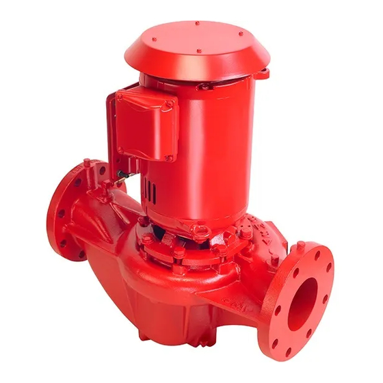
水ポンプ Armstrong 4360DのPDF サービス作業指示書をオンラインで閲覧またはダウンロードできます。Armstrong 4360D 3 ページ。 Close coupled vertical in-line pump (jm/jp motor frame)

ASSEMBLY PROCEDURES:
11. REPLACE MECHANICAL SEAL
Clean the shaft sleeve [70] surface, ensuring all the former
seal elastomer pieces have been removed. Inspect for
damage. Replace if necessary. (See separate instructions
for removal of the shaft sleeve [File No. 6042.25]). Inspect
the water slinger [39] and replace if damaged
Install a new seal seat [60] in the adapter cavity, being
sure the lapped (polished) side of the insert is facing up.
Ensure that the cavity has been thoroughly cleaned. Lubri-
cate the seat O-ring or L-cup with a small amount silicon
or glycerine lubricant and press down, straight and even,
into the cavity. Do not press the seat in with bare fingers,
use a clean cloth or the cardboard disc typically supplied
with the seal. Contamination of the polished and lapped
seat face could cause leakage. If the adapter was re-
moved from the motor, replace now, taking care that the
seal seat is carefully guided over the motor shaft.
Lubricate the inside of the seal rotating assembly [62] with
a small amount of silicon or glycerine lubricant and slide
onto the shaft sleeve [70] with a twisting motion, carbon
face first, until the carbon face is pressed firmly against
the seal seat [60]. Pressing on the seal rotating assembly
metal parts, with a screw driver, all the way around the
seal, will ensure that the faces are mated properly. Re-
move the spring retainer from the seal spring and place
the seal spring over the seal rotating assembly. Series
4360D and 4380 units with frame 56C motors will have a
shaft extension in place of an extended JM/JP shaft. This
should be treated in exactly the same manner as de-
scribed above for seal replacement.
12. REPLACE PUMP IMPELLER
Install the shaft sleeve spacer [71] and impeller key on the
shaft and place the seal spring retainer onto the impeller
hub register. Slide the impeller in place on the motor shaft.
Take care and ensure that the seal spring is kept in place
on the seal rotating assembly and fits well into the retainer
on the impeller hub.
13. TIGHTEN IMPELLER CAPSCREW
It is good practice to replace self locking screws, once
removed. Install the impeller capscrew and washer [83 &
86]. Hold the impeller the same way as when the cap-
screw was successfully loosened (Bar or screw driver
placed carefully between the impeller blades) and tighten
the capscrew with a socket wrench.
S. A. Armstrong Limited
Armstrong Pumps Inc.
23 Bertrand Avenue
93 East Avenue
Toronto, Ontario
North Tonawanda, New York
Canada, M1L 2P3
U.S.A. 14120-6594
T: 416-755-2291
T: 716-693-8813
F: 416-759-9101
F: 716-693-8970
For Armstrong locations worldwide, please visit www.armstrongintegrated.com
14. INSTALL NEW CASING GASKET
Insert new casing gasket [101] into the gasket cavity in
the casing.
15. LOWER ROTATING ASSEMBLY INTO PLACE
The rotating assembly (Motor, adapter and impeller
combination) may now be lowered into place in the
casing.
16. CASING CAPSCREWS
The casing capscrews [104] are now installed and evenly
tightened with a wrench. Tighten the capscrews a little at
a time, diagonally across the casing, to assure even
gasket pressure.
Replace the flush/vent tubing assembly
17. ISOLATION VALVES
Replace the casing drain plug and open the suction and
discharge isolation valves.
18. MOTOR WIRING
The motor conduit and its wiring are now replaced. If the
motor is new, double check that the voltage and rpm are
identical to the original motor.
Be sure to check rotation of the motor after rewiring if the
motor is three phase and correct if necessary, by switch-
ing any two lead wires.
Ensure that the pump is filled with water before operating
to check rotation.
19. CONDUIT BOX COVER
The conduit box cover is replaced after checking the mo-
tor rotation. The pump may now be placed in operation.
Armstrong Integrated Limited
Wenlock Way
Manchester
United Kingdom, M12 5JL
T: +44 (0) 8444 145 145
F: +44 (0) 8444 145 146
Page 3 of 3
© S.A. Armstrong Limited 2010
