- ページ 10
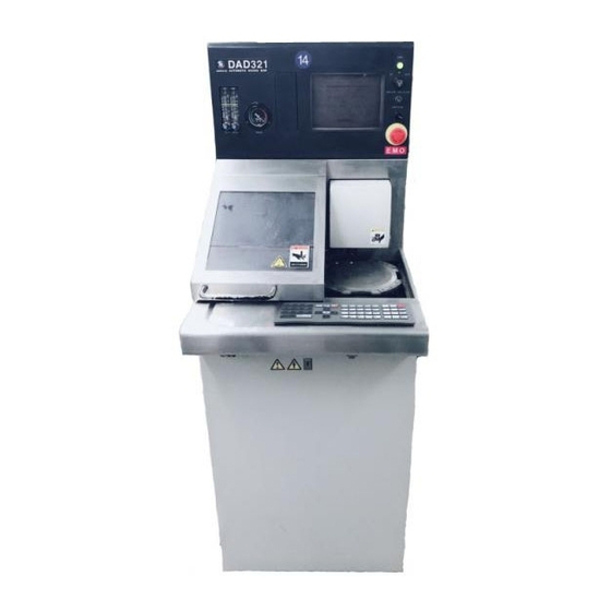
ソウ DISCO DAD321のPDF データ・メンテナンス・マニュアルをオンラインで閲覧またはダウンロードできます。DISCO DAD321 20 ページ。 Automatic dicing/cutting saws
DISCO DAD321 にも: メンテナンス・マニュアル (20 ページ)

- 1. Read Carefully before Using this Manual
- 2. Introduction
- 2. Table of Contents
- 3. Contents
- 4. C. General Description of Data Screen
- 5. Important Safety Information
- 5. General Safety Precautions
- 5. Safety Precautions to be Observed During Operation
- 5. Inherently Hazardous Areas and Ways to Avoid Hazards
- 5. EMO Switch
- 5. Operations
Axis Arrangement Diagram [321/351/361]
The diagram and the table below show axis arrangement, names and functions
of each axis.
X-axis
Y-axis
Z-axis
θ -axis
Spindle Shaft
Section
Main Body Frame
Spindle axis
θ
-axis
(except 351)
X-axis
Front
Name
Moves the chuck table to the right and the left.
Moves the spindle shaft and the microscope forward
and backward.
Moves the spindle up and down.
Rotates the chuck table.
Rotates a blade at a high speed.
Supports the machine main body.
Function
Intro-6
Z-axis
Y-axis
Main body frame
