- ページ 2
スイッチ Blake UK PROception starBOX PROSTR5SのPDF 取扱説明書をオンラインで閲覧またはダウンロードできます。Blake UK PROception starBOX PROSTR5S 8 ページ。 Distribution hubs

•
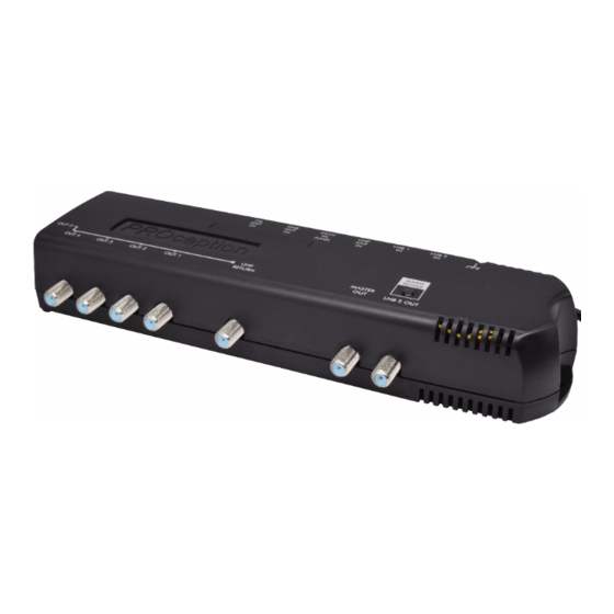
LNB 2 OUT—this is a filtered through-connection from LNB 2 IN and, where used, will usually
connect to a second SAT outlet at the master location. High- pass filtering is included in the starBOX
to prevent terrestrial signals being degraded by LNB noise which could otherwise interfere due to
crosstalk in the wiring or the master outlet plate.
•
OUT 1-5 or OUT 1-10—these are the extension room outlets and carry FM and DAB radio from the
respective aerial inputs as well as the UHF return signal connected to UHF RETURN. These outputs
do not carry satellite IF signals. Each of the five or ten outputs is powered at approximately 9 V DC to
power an infrared receiver eye.
Important: please understand that the UHF path to the extension room outlets comes entirely from UHF
RETURN IN. There is no direct bypass from the aerial and CCTV inputs to the extension rooms. Therefore
there must always be a path or connection between MASTER OUT and UHF RETURN, otherwise no TV
signals will reach the extension rooms. This path is usually provided at the master location, as explained
above. In the event that no master equipment is installed, a link should be connected between MASTER
OUT and UHF RETURN either at the master outlet plate or directly at the starBOX unit in order to provide
TV signals in the extension rooms.
Remote control option:
Using a magic infra-red eye (e.g. PROception PROSAT1EYE) enables remote control. However, this can
only be used to control a Sky Digibox or Sky+ PVR. The remote receiver eyes communicate directly with
the Sky* equipment and it is essential that the UHF RETURN input of the starBOX is fed directly from the
RF OUT-2 connector of the Sky* or Sky+* receiver (see connection diagram, Fig.2) or
receiver.
#
I/O Port Replicator needed for Sky box DXR850/890; See Supplementary Installation Instructions to introduce
PROception PROLINK22 'RF replicator'.
Installation notes
Installation fixed wiring plan:
The fixed wiring for a full installation is shown in Fig.1 on pages 6-7. Signal sources not required may of
course be omitted. Any number of extension rooms may be connected, up to the maximum of five or ten
for the PROSTR5S and PROSTR10S units respectively. The diagram also shows how the two spare outputs
from a quad LNB can be wired to single F outlets in an extension room/s to allow additional local satellite
equipment to be used. In this case a separate Sky* or Sky+* receiver will be needed at this location.
starBOX location and fixing:
Choose a suitable central location to fix the starBOX unit. The location must be dry and not subject to
prolonged ambient temperature conditions of less than -10 °C or more than +40 °C.
Fix the starBOX unit to a sound vertical surface such as a wall or equipment mounting board. Ventilation
gaps of at least 50 mm should be left around the front and all sides of the unit. More clearance will be
required above, below and to the left of the unit to allow access for the signal cables.
Do not install the unit where it could become smothered with curtains or other soft furnishing fabrics or
leave it resting on a carpet. When installing the unit in a roof space or similar building void ensure that
it will not come into contact with thermal insulation material.
Cables and signal connections:
To preserve RF screening integrity the signal connections to the unit should be made using good quality
coaxial cable and connectors. This is particularly important with digital terrestrial TV (DTT) to minimise
the ingress of impulsive electrical interference from home appliances and with digital satellite TV to
prevent missing channels. The use of cable benchmarked under the CAI scheme is recommended. All
signal connections are made with Type-F connectors. The use of good quality crimp connectors, used in
accordance with the manufacturer's instructions will give the best results. The importance of achieving
sound braid connections cannot be over-stressed. Completed connections should always be tightened
with a spanner; leaving them finger-tight can sometimes lead to poor connections and attenuation of the
signal. If the CCTV input is not used, the 75Ω terminator plug supplied must be left in place. Any other
unused connectors may be left open.
#
I/O port
of the Sky
