- ページ 5
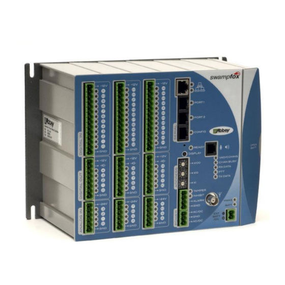
コントローラー Abbey swampfox SF1のPDF インストレーション・マニュアルをオンラインで閲覧またはダウンロードできます。Abbey swampfox SF1 8 ページ。 Pump station controller

Serial Ports
Name
Type
PORT 1
RS-232
PORT 2
RS-232
CONFIG
RS-232
(1)
Connector pins 2 and 3 are not connected on
(2)
The +12V outputs can power small loads such as serial
converters.
Each port has a red/green LED indicator, which blinks green
when
receives a valid message. Red indicates an error
swampfox
condition.
Serial ports can be permanently damaged if an
Ethernet cable is plugged into them.
Ethernet Port
This is a standard 100-base-T Ethernet port, which is operational when the
appropriate firmware is installed.
External Radio Connections
These connections are applicable only when no internal radio is fitted.
8
RJ45 Pins
Always use best radio-frequency engineering
practices for all radio and antenna installation.
Connect an antenna before powering up swampfox
IG-619-2.2-2015-Mar
Typically used for...
Socket
(1)
RJ-45
Local connection to PLC, data logger, meter
RJ-45
Local connection to PLC, data logger, meter
RJ-45
Laptop, Analog output module
1
.
PORT 1
Pin
1
2
3
4
5
6
7
8
4
Dir
1
sf +12V
(1)
2
sf COut2
(1)
3
sf CIn2
4
sf COut1
5
sf CIn1
6
sf TxD
7
sf RxD
8
Dir
Name
GND
sf
PTT
sf
Channel Busy
sf
Tx Audio
sf
Rx Audio
sf
Serial TxD
sf
Serial RxD
GND
Installation Guide
Name
(2)
GND
