- ページ 6
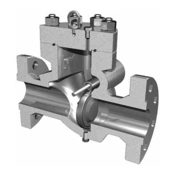
コントロールユニット Cameron WHEATLEY 500 SeriesのPDF インストレーション、オペレーション、メンテナンスマニュアルをオンラインで閲覧またはダウンロードできます。Cameron WHEATLEY 500 Series 9 ページ。 Swing check valve

7. If the valve, in service, is exposed to hazards such as traffic, wind or earthquake loading, contact the
factory, if it is necessary, to confirm that the valve design is suitable for the application. The factory
requires a complete description of the hazard before making any recommendations.
8. If the valve, in service, is exposed to hazard s such as excessive piping system reaction forces and
moments, contact the factory, if it is necessary, to confirm that the valve design is suitable for the
application. The factory requires a complete description of the hazard before making any
recommendations.
9. If the valve, in service, is exposed to hazard s such as corrosive or abrasive fluids or atmospheric
conditions, contact the factory, if it is necessary, to confirm that the valve design is suitable for the
application. The factory requires a complete description of the hazard before making any
recommendations.
10. The valve has been designed and manufactured so that under normal operation conditions hazards such
as material fatigue, brittle fracture, creep rupture or buckling will not occur. Do not operate the valve
beyond the pressures and temperatures marked on the nameplate. The factory requires a complete
description of the hazard before making any recommendations.
11. The user is responsible for minimizing other hazards associated with the construction, operation, and
maintenance of high pressure piping systems, such as:
a.
Provisions for the release or blow off of pressure
b. Prevention of physical access to system under pressure
c.
Prevention of physical access to surfaces at extreme temperature
d. Provisions for inspection
e.
Provisions for draining and venting
f.
Provisions for filling
g.
Provision for equipment access
h. Prevention of over-pressurization, over-heating and over-filling
i.
Provision for fault indication
12. The user is responsible for meeting applicable local safety regulations.
NOTE: If system hydrostatic tests are to be performed at pressures exceeding the rated working pressure of the
valve, the valve should be pressurized from the upstream side. This prevents the clapper from experiencing these
pressures while the body cavity can accept up to 150% rated working pressure. Care must be taken not to damage
the seal faces and that they are clean for assembly. The end-user must provide gaskets and mating flanges of equal
ratings to that of the valve for proper installation. When bolting the flanges together, threads of bolts should be
lubricated to obtain the maximum loading on the bolts. The bolts should be tightened using a crisscross pattern for
even loading. When ring type joints are supplied, the ring number is marked on the rim of the RTJ flange. After
pressure tests, with all test pressure relieved, the body cavity should be completely drained via the attached piping
system to prevent corrosion. The valve may then be placed in the required operating position.
HORIZONTAL INSTALLATION
TC-003001-13/ Rev 02
6
