- ページ 5
コントロールユニット Cameron WHEATLEY 822 SeriesのPDF インストレーション、オペレーション、メンテナンスマニュアルをオンラインで閲覧またはダウンロードできます。Cameron WHEATLEY 822 Series 8 ページ。 Swing check valve

INSTALLATION & OPERATION
NOTE: If system hydrostatic tests are to be performed at pressures exceeding the rated working
pressure of the valve, the valve should be pressurized from the upstream side. This prevents exposure
of the clapper to these pressures while the body cavity can accept up to 150% rated working pressure.
Care must be taken not to damage the seal faces and that they are clean for assembly. After pressure
tests, with all test pressure relieved, the body cavity should be completely drained via the attached
piping system to prevent corrosion. The valve may then be placed in the required operating position.
HORIZONTAL INSTALLATION
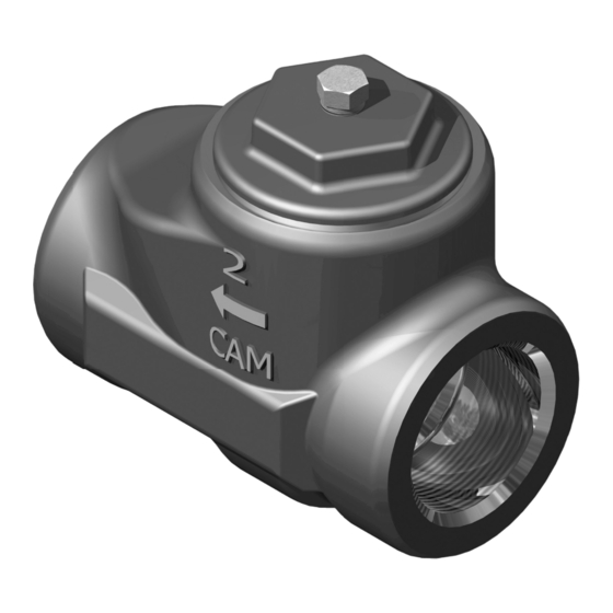
When installing the swing check valve in the horizontal position, install the valve with the arrow mark
on the body pointing in the direction of flow and the cover side up.
OPERATION
Flow through the valve (in the direction of the arrow mark) forces the clapper to lift fully. The
clapper seals the valve when the flow is reversed. Gravity causes the clapper to swing closed
when no flow is present.
VERTICAL INSTALLATION
When installing the swing check valve in vertical piping, install the valve with the arrow mark on the
body pointed in the upward direction. Upward flow through the valve will cause the clapper to swing
open. This valve cannot be used with vertical downward flow.
OPERATION
If there is no flow through the piping, gravity will keep the clapper in the closed position. Flow
through the piping in the upward direction will cause the clapper to swing open. When the
flow is reversed, the flow and weight of the clapper will automatically close the valve.
Installation, Operation and Maintenance Manual
5
D I S T R I B U T E D V A L V E S
02/2011 / IOM-WHE-CHECK-822
