- ページ 17
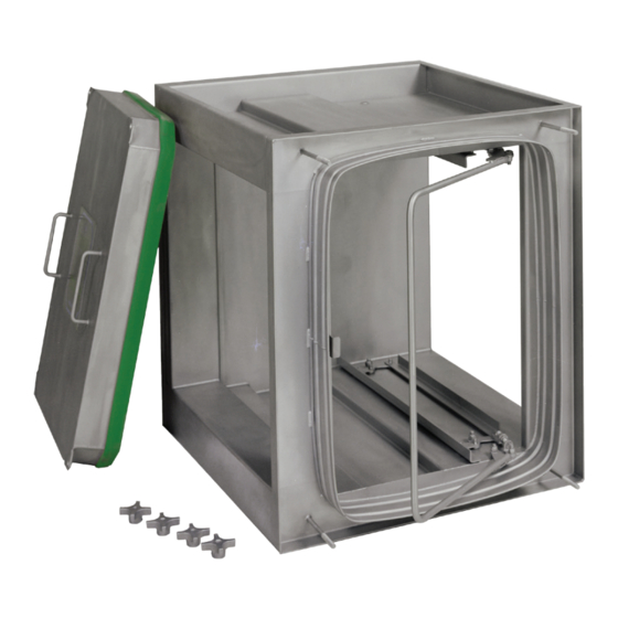
浄水器 Camfil FB SeriesのPDF インストレーション、オペレーション、メンテナンスマニュアルをオンラインで閲覧またはダウンロードできます。Camfil FB Series 20 ページ。 Fluid seal bag-in/bag-out

5. Install replacement locking mechanisms and secure with 3/8" locknuts which were removed from replaced
locking mechanism. Note: Before replacing new locking mechanism, be sure the nylon washers are
around studs. Tighten 3/8" locknuts securing locking trays to housing, then loosen the locknuts 1/4 turn
(This step is critical to allow free movement of the locking tray). Install locking handle by sliding
adjustment studs through linkage tabs, and pivot arms through 5/16" studs connected to housing. Tighten
5/16" locknuts on pivot arms, then loosen 1/4 turn (This step is critical to allow free movement of the
locking handle).
6. Using the dimension that was recorded in step 3, tighten 3/8" locknuts on adjustment studs. This may
require adjusting the inside 3/8" nut to the correct dimension also. To assure there is free movement of
both locking trays, open and close locking mechanism several times with the locking handle (push to close,
pull to open).
1. When installing filter(s)/adsorber(s) and/or closing the locking mechanism, do not force the handle closed.
The locking mechanisms are preset at the factory (when installed in a filtration system from the factory) with
the correct tension on the locking handle. The handle should move fairly easily until within approximately
1" of the locking handle latch, then moderate pressure should be applied to latch and secure the handle. If
the handle takes more than moderate pressure to latch, the locking mechanism adjustment should be
corrected for the proper tension.
2. Excessive tension: To adjust the tension of the locking handle, locate the 3/8" locknuts on the adjustment
studs (one on top, one on bottom), refer to Detail No. 2. If there is excessive tension on the locking
mechanism handle, adjust the 3/8" locking nuts by turning counter-clockwise until the proper tension is
achieved. Tighten the inside nuts back up to the locknuts.
3. Insufficient tension: To adjust the tension of the locking handle, locate the 3/8" locknuts on the
adjustment studs (one on top, one on bottom), refer to Detail No. 2. If there is insufficient tension on the
locking mechanism handle, loosen the inside nuts and adjust the 3/8" locking nuts by turning clockwise until
the proper tension is achieved. Tighten the 3/8" locknuts back to the inside nuts.
Locking Mechanism Adjustment
17
