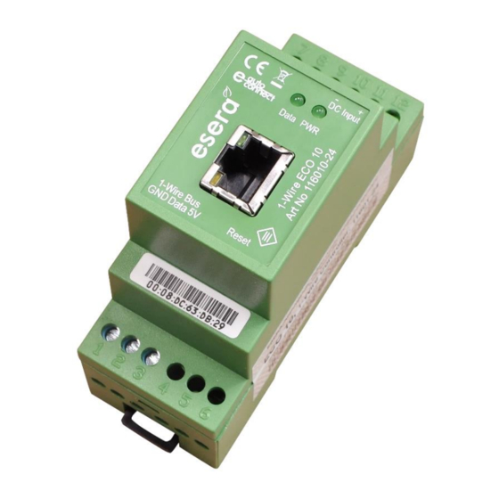
- ページ 4
コントローラー esera automation ECO 10のPDF ユーザーマニュアルをオンラインで閲覧またはダウンロードできます。esera automation ECO 10 13 ページ。 1-wire controller

4
Technical data
Ethernet interface:
Auto-E-Connect:
Data, Firmware Update
and Configuration
Software Support:
Supply voltage:
Current consumption
Power supply RTC:
1-Wire interface :
Protective circuits:
Connection:
Output voltage:
Isolation:
Supported
1-Wire Devices:
5
Ambient conditions
Operating temperature: -5°C to +50°C
Storage temperature:
Relative humitidy:
Room classification:
Protection system:
Protection class:
Dimensions:
6
Conformity
EN 50090-2-2
EN 61000-4-2, ESD
EN 61000-4-3, HF
EN 61000-4-4, Burst
EN 61000-4-5, Surge
EN 61000-6-1, Interference immunity
EN 61000-6-3, Interference radiation
RoHS
7
Display LED
The module has various indicator LEDs.The function oft he displays is as follows
Display
LED Green
LED Green
LED Yellow
data interface
LED Green
data interface
* if the sensor or actuator supports Auto-E-Connect. For details, please refer to the operating instructions of the sensor or actuator.
All rights reserved. Reproduction as well as electronic duplication of this user guide, complete or in part, requires the written consent of
ESERA GmbH. Errors and technical modification subject to change. ESERA GmbH 2021
www.esera.de
TCP/IP or UDP, Socket Server or Client
- 10/100 MBit Ethernet Interface (RJ45)
- Auto Negotiation (Full-duplex and Half-duplex)
- Auto MDI/MDIX
- Support für DHCP and fixed IP-Adresse
Level I and II supported
Auto-E-Connect Level III is only supported from ECO 100 onwards
ESERA Config Tool 3
ECO Dashboard 100
9-30VDC
max. 1000mA
Goldcap, Buffering of the internal clock (RTC) in the event of a supply voltage failure for
approx. 2 days. In the event of a longer failure, the RTC must be reset. The gold cap is
charged after approx. 2 hours.
1-Wire Bus (+5V, ground (GND) and Data)
ESD-, overvoltage and reverse polarity protection
Screw terminals (up to 2.5qmm cable cross-section)
+5V (+/-10%), max. 300mA, overload, overvoltage and short-circuit protected
Galvanic isolation between Ethernet and 1-Wire interface
DS2401, DS1963, DS1990, DS1820, DS18S20, DS18B20, DS2413, DS2438, DS2450
DS2408, DS2405, DS2406 (input only), DS2423, other chips on request. We will be
happy to support further components as an OEM product for you.
-20°C to +70°C
10% bis 92% (non condensing)
Operate only in dry rooms
IP20
III
35 x 90 x 70mm (WxHxD)
Designation
Function
PWR
Display for supply voltage
DATA
Network Link LED,
Lights up when there is a network connection
Network Data LED
Lights up when there is data traffic via the data interface
11601-24 V1.0 R1.1 Manual
After switching on the unit, the LED flashes 3x
flashes during 1-Wire activity
flashes when sending data via the data interface
flashes very quickly if "KAL Receive" has been
activated and the "KAL Messages" of the control
system are missing.
Page 4 of 13
