- ページ 5
ゲートウェイ esera automation 11337のPDF ユーザーマニュアルをオンラインで閲覧またはダウンロードできます。esera automation 11337 10 ページ。 W/auto-e-connect

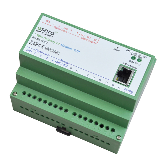
Art. No. 11337
Module bottom side (power supply, digital input and analog output)
1 = GND/negative digital input isolated to negative supply
2 = digital input 1 10 – 30 VDC
3 = digital input 2 10 – 30 VDC
4 = digital input 3 10 – 30 VDC
5 = digital input 4 10 – 30 VDC
6 = GND/ negative analog output isolated to negative supply
7 = analog output 0 – 10 VDC
8 - 15 = not assigned
16 = GND/ negative supply voltage
17 = Positive supply voltage
Module top side (Digital Output and 1-Wire Bus)
18 = main supply for digital output 1+2
19 = digital output 1, max. 8 A
20 = digital output 2, max. 8 A
21 = main supply for digital output 3+4
22 = digital output 3, max. 8 A
23 = digital output 4, max. 8 A
24 = digital output 5 break contact, max. 5A
25 = main supply for digital output 5
26 = digital output 5 make contact, max. 5A
30 = Reset Button inside
32 = GND/ negative 1-Wire Bus
33 = 1-Wire Data
34 = 5 V voltage supply for 1-Wire Bus, max. 200 mA
35 = 12 V voltage supply for 1-Wire Bus, max. 250 mA
Basics and tips for 1-Wire Bus systems can be found in our webshop (https://www.esera.de/1-wire-rundlagen/)
or in our e-book which is also available in our webshop
(https://www.esera.de/service-
support/dokumentation/352/grundlagen-1-wire-bus-ebook?number=11901).
All rights reserved. Reproduction as well as electronic duplication of this user guide, complete or in part, requires the written consent of
ESERA GmbH. Errors and technical modification subject to change. ESERA GmbH, ESERA-Automation 2020
www.esera.de
11337 V2.0 R1.0 Manual
Page 5 of 10
