- ページ 3
ゲートウェイ esera automation auto connect 11324のPDF ユーザーマニュアルをオンラインで閲覧またはダウンロードできます。esera automation auto connect 11324 8 ページ。 1-wire gateway 10 modbus rtu

Art. No. 11324
6
Environmental conditions
Temperature, operation -10°C to +55°C (extended temperature range possible on request)
Humidity:
Protection system:
Protection class:
Dimensions:
7
Conformity
EN 50090-2-2 EN, 61000-4-2 ESD, EN 61000-4-3 HF, EN 61000-4-4 Burst, EN 61000-4-5 Surge, EN 61000-6-1
Störfestigkeit, EN 61000-6-3 Störstrahlungen, RoHS
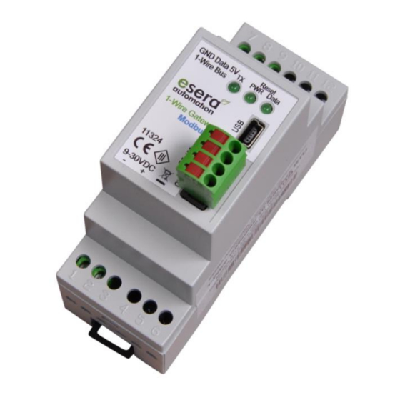
The module has different display LED´s. Following the function of the displays
8
Display LED
The module has different display LED´s. Following the function of the displays
Anzeige
LED Green
LED Green
LED Green data
interface
9
Wiring diagram
module top side, 1-Wire Bus
7 = Ground 1-Wire
8 = 1-Wire Data
9 = + 5V output
11 = Reset Button
module bottom, voltage
power supply 9-30VDC
1 = Minus supply voltage
2 = Plus supply voltage
10
Terminating resistor /
termination RS485 interface
Within the 1-Wire Gateway 10 there is a termination or termination resistor with 120 Ohm. You can activate
this by establishing a cable connection between PIN A and A_R of the RS485 connector.
All rights reserved. Reproduction as well as electronic duplication of this user guide, complete or in part, requires the written consent of
ESERA GmbH. Errors and technical modification subject to change. ESERA GmbH, ESERA-Automation 2020
www.esera.de
10 - 92% (non-condensing)
IP20
III
35 x 90 x 70mm (WxHxD)
Bezeichnung
Funktion
PWR
Display for supply voltage
DATA
TX
Send LED,
Lights up when data is sent via USB and RS485 interface
11324 V2.0 R1.0 Manual
After switching on the device, the LED flashes 3 times.
Flashes during 1-Wire activity
Flashes when data is being sent via the interface port
Flashes very quickly if "KAL Receive" has been
activated and the "KAL messages" of the control
system do not appear.
Page 3 of 8
