- ページ 2
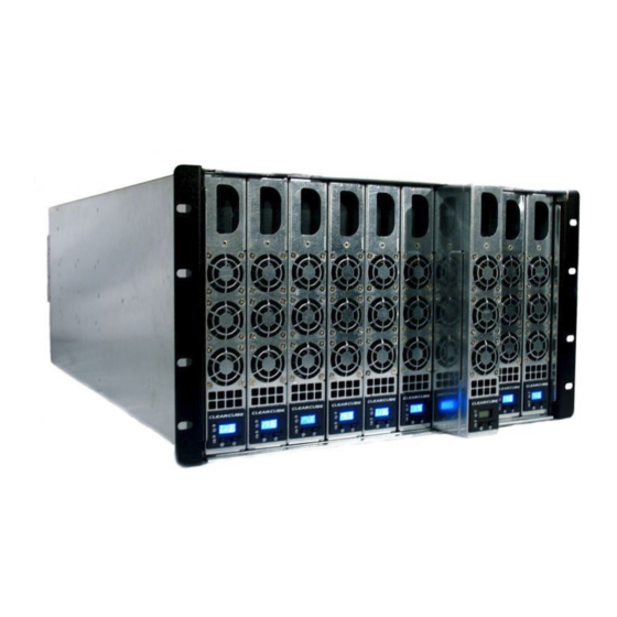
エクステンダー ClearCube A3100のPDF クイック・スタート・マニュアルをオンラインで閲覧またはダウンロードできます。ClearCube A3100 3 ページ。 Upgrading
ClearCube A3100 にも: クイック・スタート・マニュアル (2 ページ), クイックスタート (2 ページ), クイック・スタート・マニュアル (2 ページ)
brackets, two back brackets, and mounting hardware. The
optional ClearCube Chassis Rapid-Mount (CRM) kit fits
standard four-post racks with square mounting holes for
snap-in rack nuts.
Installing the Ground Strap
After installing the A3100 chassis, use the included 10-32
screws to attach the ground strap to the ground point on the
right-hand side of the AC tray and to the rack or cabinet in
which the A3100 chassis is installed. Ensure that the rack or
chassis is properly grounded. See the figure below.
AC Tray
NOTE
To screw the ground strap to a rack, insert a
snap-in rack nut. A rack nut is not provided in
the kit.
Power Inputs and Failover Power Feature
CAUTION: High Leakage Current
Connect chassis earth ground before supplying
AC power to chassis.
Be sure to connect the chassis ground strap (as explained in
the section above) before connecting power.
As shown in the figure below, the A3100 chassis has four
power receptacles: two for each half of the chassis providing
power and redundant power.
• Receptacles A and B power Blade PCs in slots one
through five.
• Receptacles C and D power Blade PCs in slots six
through ten.
ClearCube Technology, Inc.
Ground Strap
3700 W Parmer Lane
Austin, Texas 78727
The picture below shows the A3100 power receptacles.
Power Receptacles for
Blades 6 to 10
D
C
Power indicator LEDs are below each power receptacle.
LEDs are illuminated when receptacles receive power.
To enable the A3100 failover power feature, connect power
to all power inputs:
• Receptacles A and C provide primary power.
• Receptacles B and D provide failover power. Connect the
cords in receptacles B and D to a backup power supply,
such as a different power circuit or to a UPS.
See A–Series Setup and Installation Guide for more
information about chassis power inputs and about using the
chassis without the failover power feature.
Installing and Removing A–Series Blade PCs
CAUTION
Never lift an A3100 chassis with Blade PCs installed.
To install an A–Series Blade PC
1. Open the chassis front bezel by pressing in on the latch
located on the upper-right side of the chassis.
NOTE
When pressing the latch to open the front
bezel, hold the bezel with one hand to ensure
that the bezel does not fall.
(512) 652-3500
Page 2 of 3
Power Receptacles
for Blades 1 to 5
B
A
www.clearcube.com
G020097 Rev C, 1.2.06.05.2013