- ページ 11
ラック&スタンド bamar BFBMESS 280のPDF 取扱説明書をオンラインで閲覧またはダウンロードできます。bamar BFBMESS 280 20 ページ。
C
C-4
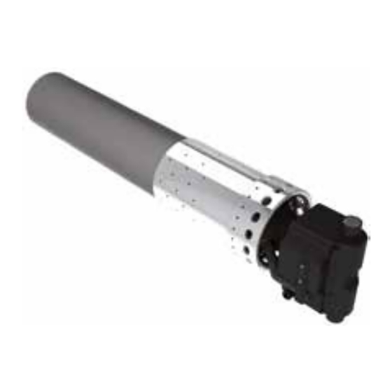
SNODO BOMA CON EMERGENZA MANUALE
280/360
C-5
MONTAGGIO DELLO SNODO-BOMA CON
EMERGENZA MANUALE
1. Viti di fissaggio perni antirotazione
2. Perni antirotazione emergenza
3. Viti accoppiamento corpo anteriore e posteriore
4. Corpo anteriore snodo boma
5. Viti di fissaggio ruota dentata
6. Ruota dentata con sede perno snodo boma
7. Spine
8. Vite senza fine - innesto manovella
9. Flangia posteriore
10. Corpo posteriore snodo boma
11. Perno snodo boma
12. Snodo boma (gruppo riduttore manuale)
13. Motorizzazione boma
14. Terminale ad occhio integrato nella motorizzazione
Per installare il gruppo riduttore manuale snodo boma, bisogna seguire
le seguenti fasi:
•
svitare le viti 1
•
estrarre i perni 2
svitare le viti 3
•
•
aprire il gruppo corpo 4 / 10
•
svitare viti 5
sfilare la ruota dentata 6 dalle spine 7
•
•
sfilare il perno 11
•
a questo punto si può inserire il terminale ad occhio 14 all' interno
della rimanente parte ancora assemblata (gruppo 7, 8, 9, 10)
•
inserire il perno 11
•
rimontare la ruota dentata 6 e proseguire a ritroso con le operazioni
su elencate.
um_bfbmess_it-en_rev. 1.0
ISTRUZIONI DI MONTAGGIO E USO
INSTALLATION AND USE
13
2
1
11
2
1
Per 280/360
For 280/360
C-4
BOOM TOGGLE WITH EMERGENCY CLUTCH
280/360
C-5
HOW TO INSTALL THE SPECIAL BOOM
TOGGLE WITH MANUAL EMERGENCY
CLUTCH
14
10
2
12
1
8
7
6
9
1. Pin locking antirotation screws
2. Anti-rotation pins for emergency clutch
3. Front and rear body coupling screws
4. Boom toggle front body
5. Crown wheel locking screws
6. Crown wheel with boom toggle pin housing
7. Plug
8. Endless screw - handle clutch
9. Rear flange
10. Boom toggle rear body
11. Boom toggle pin
12. Boom toggle (manual reduction gear group)
13. Boom motorization
14. Motorization integrated eye terminal
In order to install the manual reduction gear group of the boom toggle,
you need to carry out the following operations:
•
unscrew screws 1
extract pins 2
•
•
unscrew screws 3
•
open the body group 4 / 10
unscrew screws 5
•
•
take off the crown wheel 6 from plug 7
•
take off the pin 11
at this stage, you may insert the eye terminal 14 inside the remaining
•
assembled part (group 7, 8, 9, 10)
•
insert pin 11
•
fit the crown wheel 6 and proceed following backwards the stages
indicated above.
5
4
3
11