- ページ 10
電源 Altronix AL1012ULMのPDF インストレーション・マニュアルをオンラインで閲覧またはダウンロードできます。Altronix AL1012ULM 17 ページ。 Multi-output access control power supply/chargers
Altronix AL1012ULM にも: インストレーション・マニュアル (17 ページ), インストレーション・マニュアル (17 ページ)
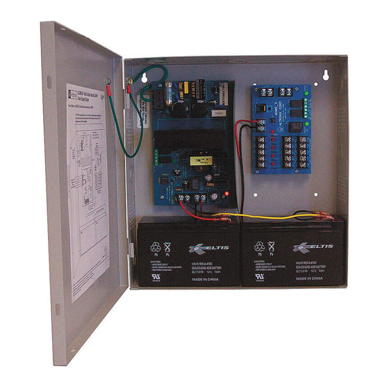
Power Supply Board
Terminal Legend
Function/Description
L, G, N
Connect 115VAC 60Hz to these terminals: L to hot, N to neutral.
AL300ULM - 12VDC/24VDC @ 2.5A to MOM5 board (power-limited).
AL400ULM - 12VDC @ 4A or 24VDC @ 3A to MOM5 board (power-limited).
+ DC –
AL600ULM - 12VDC/24VDC @ 6A to MOM5 board (power-limited).
AL1012ULM - 12VDC @ 10A to MOM5 board (power-limited).
AL1024ULM - 24VDC @ 10A to MOM5 board (power-limited).
Indicates loss of AC power, e.g. connect to audible device or alarm panel. Relay normally energized when
AC FAIL
AC power is present. Contact rating 1A @ 28VDC. AC or brownout fail is reported within 1 minute of event.
NC, C, NO
To delay reporting for up to 6 hrs., cut "AC delay" jumper and reset power to the unit.
Indicates low battery condition, e.g. connect to alarm panel. Relay normally energized when DC power is
present. Contact rating 1A @ 28VDC. A removed battery is reported within 5 minutes. Battery reconnection
BAT FAIL
is reported within 1 minute.
NC, C, NO
Low battery threshold:
12VDC output threshold set @ approximately 10.5VDC.
24VDC output threshold set @ approximately 21VDC.
Stand-by battery connections.
+ BAT –
AL300ULXB2, AL400ULXB2, AL600ULXB and AL1012ULXB (Power Supply Board)
maximum charge current is 0.7A. AL1024ULXB2 maximum charge current is 3.6A.
MOM5 - Output Module
Terminal Legend
--- DC INPUT +
TRIGGER
- - - INPUT +
NEG. 1
THROUGH NEG. 5
POS. (+) DC OUTPUT
(ALARM) 1-5
POS. (+) DC OUTPUT
(STAND-BY) 6-10
NC, C, NO
DRY OUTPUT
NC, C, NO
POWER FAIL
- 10 -
Terminal Identification Tables:
Function/Description
12VDC or 24VDC from power supply.
Dry normally open [NO] or normally closed [NC] supervised (2.2K EOL resistor) input trigger. A short
or open circuit will transfer power from terminals marked [POS. (+) DC OUTPUT (STAND-BY)] to
terminals marked [POS (+) DC OUTPUT (ALARM)].
Wet (5-30VDC) input trigger. Applying voltage to these terminals in the polarity shown will
transfer power from terminals marked [POS. (+) DC OUTPUT (STAND-BY)] to terminals marked
[POS. (+) DC OUTPUT (ALARM)] (e.g. fire alarm control panel indications circuit).
Supplies constant negative (-) voltage.
Supplies positive (+) voltage when dry trigger input or fire alarm wet trigger input is applied.
Supplies positive (+) voltage in normal condition. Power is removed when dry trigger input
or fire alarm wet trigger input is applied.
When the MOM5 is triggered the terminals marked [C and NO] will open and the terminals marked [C
and NC] will close. This output is used to trigger auxiliary devices. (e.g. HVAC Shutdown, Elevator
Recall etc.) Contact rating 1A @ 28VDC.
Form "C" contacts used for reporting no voltage is present at [-- DC INPUT +] terminals.
Under normal conditions, terminals marked [NO and C] are open, [NC and C] are closed.
A loss of power causes terminals marked [NO and C] to close and [NC and C] to open.
Contact rating 1A @ 28VDC.
M series