- ページ 5
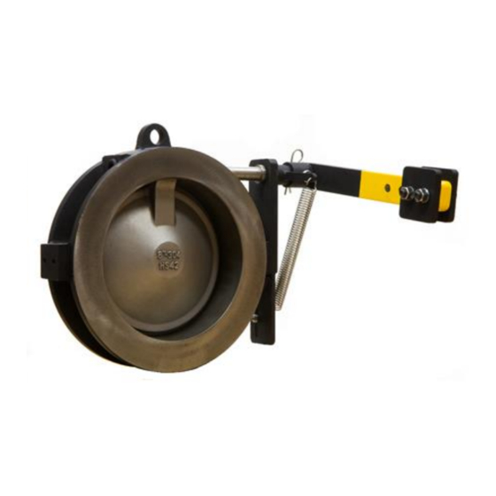
コントロールユニット CVI SDXのPDF マニュアルをオンラインで閲覧またはダウンロードできます。CVI SDX 7 ページ。 Single disc external spring check valve
NOTE: EYE PROTECTION IS RECOMMENDED WHEN DISASSEMBLING AND ASSEMBLING CHAMPION
CHECK VALVES.
DISASSEMBLY
Disassembly and assembly of the SDX Check valve is moderately simple using a hammer, allen-wrench,
bronze round nose punch and Locktite thread sealant and the following instructions:
Please use caution when removing/installing the external spring. Preset spring(s) may cause serious
injury when tension is released.
1. Lay the body down with downstream side facing upward.
2. Using an allen-wrench, remove the plug on the opposite side of the body from the spring.
3. Remove set screws on the spring side of the valve holding the bracket to the valve body.
4. Carefully detach the spring from the spring adaptor and eye bolt by first removing loop through
eye bolt and then by removing spring from spring adaptor arm. Spring may have tension so be
careful in this step. Removing a loaded spring can cause serious injuries if done without caution.
5. Using a hammer, gently knock the pin out of the spring adaptor using a small punch and slide
the spring adaptor off of the shaft.
6. Remove the bracket from the valve body. It should be easily pulled off but a hammer can be
used to gently tap it off if it becomes stuck.
7. Using a hammer, gently tap out the shaft from the side opposite of the spring. This will allow the
shaft with the o-rings installed to slide out and if done correctly shouldn't cause additional
damage to any internal components.
8. After the shaft is removed, the disc and bushings can be lifted out of the valve from the outlet
side and the valve should be completely disassembled.
ASSEMBLY
1. First lay the body down with downstream side facing upward.
2. Ensure that the seat is installed correctly in the body of the valve. Champion does not
recommend performing a seat change, contact Champion if any concerns arise about the seat's
viability before reassembling the valve.
3. Place the disc down inside the body with the flat face resting against the seat, about where it
will be installed to have it ready for the shaft to be assembled.
4. Place new o-rings onto the shaft in the correct position, indicated in the assembly drawing
above.
5. Insert the shaft from the spring side of the valve stopping when the shaft starts to protrude into
the center of the valve where the disc is sitting.
6. Place the first bushing over the shaft on the spring side of the disc and then proceed to push
shaft through the bore of the disc, stopping once it protrudes past the disc bore.
P.O. B
12901, WILMINGTON, NC 28405
OX
P
: 910-794-5547 - F
HONE
W
:
.
EBSITE
WWW
WAFERCHECK
: 910-794-5581
AX
.
COM