- ページ 2
おもちゃ Fleischmann 145 SeriesのPDF 操作説明をオンラインで閲覧またはダウンロードできます。Fleischmann 145 Series 4 ページ。
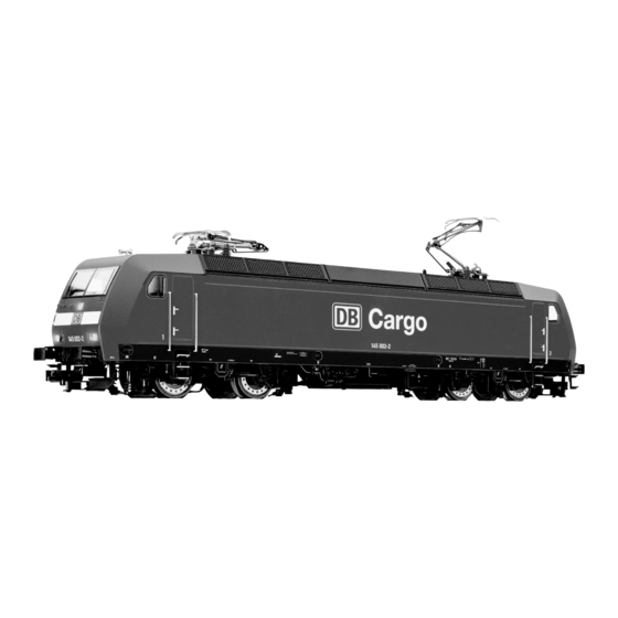
Fig. 2
Stromzuführung über Oberleitung:
Stromzuführung über Gleis:
Schalter in Position "Pantograph" stellen.
Schalter in Position "Gleis" stellen (Werkseinstellung).
1
j
Fig. 3
Durch das neue Antriebskonzept mit Mittelmotor
pfän gerbausteins erforderlich. Lok gehäuse in der Mitte
und Kardanwellen sind die Dreh gestelle im Gegen-
aufspreizen und nach oben abheben (Fig. 3). Beim Auf-
satz zu früheren FLEISCHMANN-Elloks nicht mehr
setzen des Gehäuses darauf achten, dass sich der Füh-
nach unten abziehbar.
rer stand 1 auf der Fahrgestellseite mit der Aus sparung
für den digitalen Empfängerbaustein (schraffiert) befin-
Öffnen: Ein Öffnen der Lok ist nur zum Lampenwechsel,
det.
Austausch des Motors und Einbau eines digitalen Em-
21-4324-0102.indd 5-8
Ölen: Geölt werden die Achsen nur an den
gekennzeichneten Stellen (Fig 5). Nur
FLEISCHMANN-Öl 6599 verwenden. Nur
ein kleiner Tropfen pro Schmierstelle (rt),
sonst Überölung. Zur Dosierung die in der Ver schluss-
kappe der Ölflasche angebrachte Nadel verwenden.
Die Motorlager dürfen unter keinen Umständen geölt
werden, der Motor ist wartungsfrei!
Die Motorschleifkohlen sind nicht austauschbar!
Lampenwechsel:
Glühlampe aus der Halterung nach oben herausziehen
(Fig. 4).
Ersatzglühlampe (weiß): 00006538 (DCC: 00006535)
Ersatzglühlame (rot):
Fig. 4
Ersatzhaftreifen:
Ersatzmotor:
Fig. 5
An der markierten Stelle kann der Schaltmagnet
Dieser
942701 befestigt werden (Fig. 5).
"gmeinsame Seite" der Lok (Fig. 5).
Ausbau des Motors
Lokgehäuse nach oben abnehmen. Die beiden
2
e
e
Schrau ben a und b am Armaturenteil lösen, das Ar-
maturenteil je doch nicht abnehmen (Fig. 7)! Die
Lok hinstellen. Die beiden Haltestifte c aus den
Drehge stellen her aus ziehen. Das Lokfahrgestell d
nach oben abheben. Dabei lösen sich die Kardan-
wellen aus den Auf nah men in den Drehgestellen. Das
Armaturenteil und die beiden Dreh ge stelle bleiben
miteinander verbunden auf der Unterlage stehen.
e
e
Die vier Halteklammern e nach außen ziehen (Fig. 6).
Die bei den Platinen f und g
Motor halte klam mer h lösen und Motor herausneh-
men. Die beiden gelben Kardanwellen i aus der Achs-
Fig. 6
halterung ziehen.
1
00006539 (DCC: 00009531)
00544006
00504355
c
i
942701
c
Stern
bezeichnet
die
masseführende
Fig. 7
Einbau des Ersatzmotors
Die beiden gelben Kardanwellen i in die Achs halte-
rungen des Ersatzmotors einklipsen. Motor in das
Lok fahrgestell einsetzen. Dabei auf die richtige Ein-
bau lage achten: die schwarze Motor mar kierung
muss auf der Seite des Fahrgestells liegen, in der
(Fig. 7) abnehmen.
sich die Aussparung für den digitalen Empfän-
gerbaustein befindet. Motor durch Auf setzen der
Hal te klammer h fixieren.
Fig. 8
2
g
d
c
i
h
c
f
Class 145/146 with variants
The Class 145 of the Deutsche Bahn (German Railways) was originally developed from the electric loco 12X from Adtranz. Also from this type, using a
modular construction form, has come the Classes 101, 145/146 and 152. In contrast to the Class 101, of which several parts have been utilised for
the 145, with a power rating of 6400 kW, she develops 4200 kW, runs at 140 km/h and develops a train haulage power of 300 kN. Even though she
rightly belongs to the goods traffic business sector (DB-Cargo), she can also be used on hauling Regional trains.
Current pick-up from the catenary: Set the switch to "pantograph" position.
a
b
Current pick-up from the track: Set the switch to "track" position.
Because of the new style of drive transmission, with central motor and cardan shaft drive, the bogies cannot be removed by simply pulling
downwards as in previous electric FLEISCHMANN locos.
Opening: Opening of the loco is only necessary for changing bulbs or motor or installing the digital module. Spread the loco body in the centre and
lift upwards (fig. 3). When reassembling the body, please make sure that the loco cab 1 is placed over the end of the chassis with the space (cross-
Die untere, kurze Platine f aufsetzen und festhalten.
hatched) to locate the digital receiver module.
Anschließend die obere, lange Platine g aufsetzen
Oiling: The axles should only be lubricated at the points indicated (fig. 5). Only use FLEISCHMANN-oil 6599. Only put a tiny drop in each place
(rt), otherwise it will be overoiled. An applicator needle is located in the cap of the oil bottle for your use. Under no circumstances should the mo-
und in die Endlage schieben. Dabei die Motor kon-
tor bearings be oiled! The motor is maintenance free!
Bulb Changing: Pull the bulb upwards out of the socket (fig. 4).
takt bleche nicht verbiegen! Beide Platinen mit den
Spare Bulb (white): 00006538 (DCC: 00006535) · Spare Bulb (red): 00006539 (DCC: 00009531) · Spare Traction Tyres: 00544006 · Spare Motor: 00504355
vier Halteklammern e sichern. Darauf achten, dass
The indicated point can be used for locating the switching magnet 942701 (fig. 5).
die beiden gelben Kardanwellen nach unten heraus-
This star indicates the so called "common side" of the loco (fig. 5).
The motor brushes are not exchangeable.
schauen. Das Lokfahrgestell auf die beiden Drehge-
Removing the motor: Lift up the loco body upwards. Undo both screws (a) and (b) on the armature piece, but do not take it out (fig. 7)! Set the loco
down. Pull the retaining bars (c) out of the bogies. Lift up the loco body d upwards. This will loosen the cardan shafts out of their sockets in the
stel le und das Armaturenteil aufsetzen. Dabei die
bogies. The armature piece and the two bogies remain joined together on the lower part. Pull the retaining clips (e) outwards (fig. 6). Take off the two
Kardan wellen in die Auf nahmen der Drehgestelle ein-
printed circuit boards (f) and (g). Undo the motor retaining clip (h) and take out the motor. Pull out the two yellow cardan shafts (i) from their bearings.
fädeln. Die Drehgestelle mit den Haltestiften c fixie-
Installation of the spare motor: Clip the two yellow cardan shafts (i) into their bearings on the replacement motor. Place the motor into the chassis.
Make sure that it is the right way round: the black motor marking must be located on the same end of the chassis where there is a space to lo-
ren. Mit den beiden Schrau ben a und b das Armatu-
cate the digital receiver module. Fasten the motor in with the retaining clip (h). Put on the lower, shorter printed circuit board (f) and hold in position.
Finally, put on the upper, longer printed circuit board (g) and slide it into the end position. Take care not to bend the motor contacts! Fasten the two
renteil festschrauben und das Lokgehäuse wieder
printed circuit boards in position using the four retaining clips (e). Make sure that the two yellow cardan shafts are pointing downwards. Place the loco
aufsetzen.
chassis over the two bogies, ensuring that the two cardan shafts slide into the sockets in the bogies. Fasten the bogies in position using the retaining
bars (c). Screw the armature piece securely in position using the screws (a) and (b) and replace the loco body.
Installing the digital receiver module: The 8-pole (NEM 652) DCC-DECODER 687503 or 10884 can be glued into the cross-hatched recess in the
loco chassis (j) (fig. 8). Please follow the instructions of the respective DECODER for installation.
Important: In DCC mode, the bulbs 00006538 (white) and 00006539 (red) must be replaced by bulbs 00006535 (white) and 00009531 (red).
Exchange couplings: Clip exchange coupling: 6511 · FLEISCHMANN PROFI-coupling: 6515.
1. Pull off in direction of arrow. 2. Insert exchange coupling in direction of arrow until clipped into position.
Einbau eines digitalen Empfängerbausteins: In die
schraffierte Aussparung des Lok fahrgestells (j) kann ein
DCC-Decoder 687503 oder 10884 mit 8-poligem Stek-
NEM
ker (NEM 652) eingeklebt werden (Fig. 8). Beim Einbau
bitte die Betriebsanleitung des jeweiligen DECODERS
beachten.
Achtung: Bei DCC-Digitalbetrieb müssen die Glühlam-
pen 00006538 (weiß) und 00006539 (rot) gegen Glüh-
lampen 00006535 (weiß) und 00009531 (rot) getauscht
werden.
j
04.06.2013 13:36:43