4.
Connect oil return lines (not included) from the circulating oil
drain holes in the bearing housings (not the housing drains)
to the 1" NPT (female) returns on the Cool Lube 2 reservoir.
Circulating oil drain hole locations are designated in the
Sleevoil Instruction Manuals. Drain hole sizes for each type of
pillow block are provided in tables above.
NOTE: All housing drains for circulating oil should be
used, if possible. Do not use housing drains.
NOTE: The circulating oil drain holes are positioned to
maintain the proper static oil level in the housings if the
circulating oil is off and the circulating oil drain holes are
open. This allows the oil rings to operate and supply oil to
the bearing in case the Cool Lube 2 is shut down or stops.
NOTE: Drain piping should be vented and as large as
possible to drain oil from the bearings at the same rate as
the incoming oil flow. The circulating oil drains must be
directed straight down into a return drain sloping away at
a 15° or greater angle.
5.
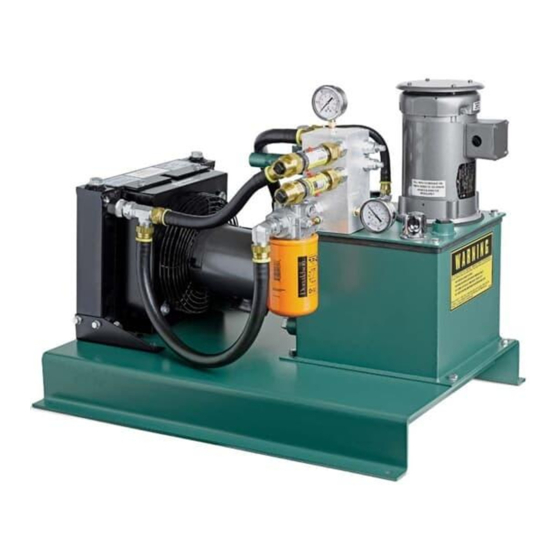
Fill up the Cool Lube 2 reservoir by monitoring the oil level
gauge on the tank. The Cool Lube 2 reservoir will hold 5
gallons of oil.
NOTE: Since the satisfactory operation of the bearing
depends almost entirely on the oil film being maintained
between the shaft and bearing liner surface, the use of a
high quality oil from a reputable manufacturer cannot be
overemphasized. Use a high grade straight mineral oil
with rust and oxidation (R & O) inhibitors and antifoam
agents. Check construction drawings or equipment
instruction manual for proper oil. Oil viscosity is
determined by the equipment manufacturer and normally
specified on the construction drawing or in the operating
manual.
6.
Fill the bearings with oil to the recommended level (see
Sleevoil Instruction Manual).
Electrical Hook Up
Connect the two electric motors to a power supply through the
proper fuses, starters and overload protection using NEC and
local electrical codes.
Optional Heater/Thermostat Assembly
260W X 120V, 1 PH—Part # 434725
260W X 240V, 1 PH—Part # 434726
Optional Temperature/Oil Level Switch
Part # 434941. Connects to a control system (not provided by
Dodge) in order to monitor oil level and temperature.
Replacement Filter
Use Cool Lube 2 replacement oil filter Part # 078358.
Optional Filter Additions
1.
Duplex filter head with two filters
2.
Water absorbing filter with moisture absorbing capability can
be added in series after the standard filter.
CAUTION: This product is not be used for person moving
application.
OPERATION
1.
Observe the oil level gauge on the tank to ensure that oil is at
the proper level.
2.
Quickly jog both motors on and off to see if they are rotating
in the correct directions (reference the rotation arrows on the
top of the motors). Correct the wiring if necessary (reverse
direction will cause damage to the pump). Before starting the
Cool Lube 2, jog the pump motor four or more times to prime
the pump.
3.
Start the Cool Lube 2 and allow the oil to circulate. Be sure to
monitor the oil level in the tank to ensure that the oil returns
from the bearing housings. If air in the return lines becomes a
problem, it may be necessary to bleed the air out of the lines
by loosening a fitting close to where the problem is.
4.
Visually check the system for leaks and correct if necessary.
5.
Confirm that there is flow by using the flow meters. If there is
no flow, check for leaks.
6.
Adjust the oil flow rates to desired flow by adjusting the
needle valves while observing the flow meters (see Figure 2).
To adjust the needle valves, first loosen the locknut, then use
an Allen wrench to open and close the valves. Make sure that
the pump pressure does not exceed 200 psi by watching the
system pressure gauge.
7.
Make sure there are no leaks of any kind.
8.
Turn off the pump.
9.
Check oil level in the tank. The oil level will go down as the oil
fills the bearing lines. If the lines are lengthy, additional oil may
be needed to restore the proper level.
10. Once the flows to the bearings are confirmed, the unit is ready
for operation.
11. Monitor the pressure gauges and oil level closely the first few
hours of operation.
12. To change the filter while the unit is running, pull and rotate
the filter bypass valve 90°.
4
MN3082
