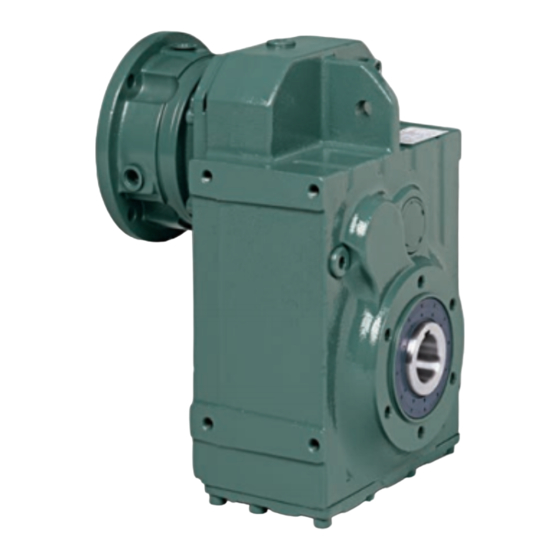
LONG-TERM STORAGE
NOTE: Unless an extended warranty has been negotiated
prior to sale, time in storage is considered time in service for
warranty purposes.
If the drive is not installed immediately, it should be stored in a
clean, dry, protected area. During periods of long term storage
(six months or longer) special procedures must be followed. The
unit should be filled to the highest oil level hole with an approved
lubricant blended with 2%, by volume, of "Daubert Chemical Co.
Nox-Rust VCI-105" oil. Apply a thick coating of rust preventative
on all unpainted surfaces including threads, bores, keyways,
and shafts. Apply a thick coating of chassis-type grease to all
exposed shaft seals. If the unit is to be stored outdoors or in a
damp, unheated area indoors, cover the entire exterior with a
rust preventative. Seal the unit in a moisture proof container
or wrapping with a desiccant inside. Shade the enclosure from
direct sunlight. Rotate the input shaft at least 60 revolutions once
a month to redistribute the lubricant and prevent brinnelling of
bearings and drying of seals.
Upon removal from storage, remove all protective coatings
applied for protection during storage. Check all hardware
for proper tightness. Drain and refill the gear reducer with a
recommended lubricant. If the gear reducer has been stored
for more than three years or in an area with high ambient
temperatures, replace the oil seals.
INSTALLATION AND OPERATION
Dodge Quantis MSM Reducers are shipped with filling, oil level
and drain plugs in place. A separate breather is included with the
unit. Before putting the unit into service the filling plug must be
replaced with the breather. Install the oil level plug and breather
plug in the correct location for the appropriate mounting position
using the mounting position diagrams shown on pages 4 through
9. Add or drain oil to get to the correct oil level for the mounting
position used.
Review the data plates on the reducer and drive motor to verify
that the drive is correct for the intended loads, speeds and power
supply. The gear reducer should be installed in a location that
meets the following requirements:
•
Ambient temperatures below 105°F (41°C)
•
Free flow of air around the motor
•
Good access to gear reducer and motor for maintenance
•
A flat, level, rigid steel mounting surface
•
All four feet of the foot-mounted unit must be evenly
supported
•
The flange mounted unit must have even support at the
flange face
•
Units supported by both flange and feet must be shimmed to
avoid housing stress
•
Good alignment to both input and output devices
Bottom of Key
Correct key t in Motor Keyway
Figure 3 – Clamp Collar Motor Key Fit
INSTALLATION OF COMPONENTS ON GEAR
REDUCER SHAFTS
Use care when installing couplings, sprockets and sheaves
(pulleys) on the Dodge Quantis MSM input and output shafts.
Such components should not be hammered into place. Damage
to shafts and bearings may result. If parts do not slip into place
easily, check for dirt or burrs that may be binding the assembly.
Very tightly fitted parts may need to be heated to get them onto
the shafts. Keys should be located for maximum engagement
between the shaft and the associated part. Sprockets and
sheaves should be mounted as close to the gearcase as possible
to minimize overhung loads. Retaining hardware (setscrews,
etc.) for couplings, sprockets and sheaves should be tightened
as recommended by the component manufacturer. Chain and
belt drives must be aligned to run true. Tighten chains and
belts according to the chain or belt manufacturer's instructions.
Excessive tension results in rapid chain and belt wear and
reduces the bearing life of the Dodge Quantis MSM unit.
2
1
Figure 1 – Three-Piece Coupling Assembly
Figure 2 – Clamp Collar Assembly
Incorrect key t in Motor Keyway
10
3
1 Reducer Coupling Hub
2 Coupling Element
3 Motor Coupling Hub
X = Distance from motor
shaft end to end face of
coupling half (the length of
X
the coupling jaws is not
included in dimension X).
1 Clamp Collar
2 Reducer Input Bore
MN1617
