- ページ 6
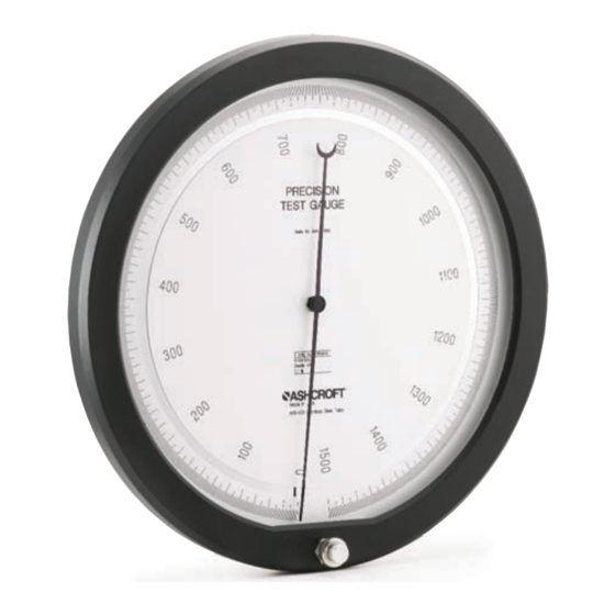
計測機器 Ashcroft a4aのPDF インストレーション&メンテナンス・マニュアルをオンラインで閲覧またはダウンロードできます。Ashcroft a4a 20 ページ。 Precision pressure gauge

Ashcroft A4A multi-coiled
Bourdon tube
pressures and special applications. See Section 7.1 for
additional information.
The Bourdon tube used in the Ashcroft A4A Gauge is a
"Unitized" single or multi-coil element which is approximate-
ly three times the length of tubes used in competitive
gauges. The greater length results in a much lower deflec-
tion rate, minimizes stress and virtually eliminates hystere-
sis, creep and fatigue effect.
The unitized tube design eliminates soldered, welded or
threaded joints which further provides for controlled distribu-
tion of stress during the tube forming operations. Internal
traps in which foreign matter may accumulate are also elimi-
nated. The interior of the Ashcroft A4A tube may be easily
cleaned by positive flow through flushing through the stan-
dard tip flushing (bleeder cap) connector.
Heat Treatment
All Ashcroft A4A Bourdon tubes are heat treated in high
vacuum to maintain internal cleanliness and optimize
mechanical properties.
Ultra-High Pressure Gauges
Ashcroft laboratories pioneered and continues to lead in the
development of precision Bourdon tubes for ultra-high pres-
sure gauges in ranges to 100,000 psi.
External Bleeder Cap
In order to achieve optimal accuracy the Bourdon tube
should be bled prior to initiating operation. If the gauge is to
be used on a gaseous media oil trapped in the Bourdon
tube should be purged from the tube. If the gauge is to be
used in liquid service trapped gas should be removed from
the Bourdon tube. Both activities are facilitated by the bleed-
er cap (flushing connector) which is an integral part of the
Bourdon tube. The bleeder cap is accessed by removing
the blow out disc from the back of the gauge.
Pressure Connection
Pressure connections may be either bottom or back loca-
tions. A complete listing of the available connections is pro-
vided in the specifications section (7.0) of this manual.
Tip Piece Assembly
The tip piece assembly is pivotally mounted on the free end
of the Bourdon tube. It comprises a quadrant and clamp
arrangement to permit adjustment of its angular position,
and a quadrant slide upon which the connecting link is piv-
oted. It is used to establish the angular relationship of the
connecting link and the sector slide which controls linearity
in the pointer movement.
Connecting Link
The Connecting Link transmits motion from the tip piece
assembly to the sector slide of the movement.
2.3.3
MOVEMENT ASSEMBL Y
Integral Movement
The solid front case provides a single rigid support for all
moving parts of the gauge, maintaining critical alignment
under all conditions. No significant calibration error will
occur in the Ashcroft A4A gauge, as a result of distortion or
shifting of supporting parts or components during the instal-
lation process.
Miniature Stainless Steel Ball Bearings
Friction and wear are minimized and sensitivity improved at
the pinion shaft by precision miniature stainless steel ball
bearings. Smooth action at this critical point in the move-
ment assures an immediate, accurate response to minute
pressure changes. This makes the Ashcroft A4A gauge the
most sensitive instrument of its type.
Gear Sector and Drive
The gear sector drives the pointer pinion directly in the
Ashcroft Model A4A precision pressure gauge. The pointer
pinion is spring loaded against backlash by a hair spring.
For maximum accuracy it is important that the original tooth
relationship be maintained throughout the system. If, for any
reason, the gears are to be disengaged they should first be
marked to assure correct re-engagement.
Hair Spring
The hair spring takes up backlash in the gearing and main-
tains the smooth sensitive action of the movement. This
spring has been pre-set to approximately 2 turns counter
clockwise with zero pressure applied. Lack of hair spring
tension will result in erratic pointer motion. Should this
occur, the gears may be disengaged, observing the precau-
tions noted above, the hair spring tightened, and the gears
re-engaged.
Sector Slide (course span adjustment)
The sector slide is mounted on the gear sector. It permits
adjustment of the ratio of pointer travel to Bourdon tube
motion by altering the multiplication through the "Micro-
Slide" adjustment. This adjustment controls the pointer trav-
el or range of the gauge (see figure 5.2).
Micro Slide Adjustment (fine span adjustment)
The micro slide adjustment provides convenient and simpli-
fied development in calibration methods. When required,
precise recalibration adjustment may be made in the total
effective length of the sector slide. The micrometer screw
attached to the slide may be adjusted to 0.0005" when
extremely minute corrections are necessary. The pre-loaded
adjustment spring stabilizes the calibration setting against
accidental shock (see figure 5.2).
6
