- ページ 5
計測機器 Ashcroft N5500のPDF 設置およびメンテナンスの取扱説明書をオンラインで閲覧またはダウンロードできます。Ashcroft N5500 8 ページ。 Capsule pressure gauge
Ashcroft N5500 にも: インストールとメンテナンスの説明 (3 ページ)

This device may optionally contain a filling liquid (e.g. glycerin or silicone oil). The provisions set out in the REACH
regulation on production and use of chemicals are to be respected, and the relevant safety data sheets from the
manufacturers of the chemicals are available on our website for download.
3 Technical data
The detailed technical information can be found in the documents in the Appendix, Chapter 11.
4 Labeling on the device
The label with the serial number and type designation is located on the outside of the housing. The materials identifier
is encoded in the type designation.
5 Construction and function
5.1 Overview
1
Case
2
Capsule
3
Process medium
4
Process connection
5
Window
6
Dial
7
Pointer
8
Bajonett ring
5.2 Description of function
The sensing element, a capsule consists of two corrugated diaphragms that are assembled pressure tight at the edge.
The pressure is led to the central point of the diaphragm and acts on the inside of the capsule. The hereby produced
lifting movement is a measure for the pressure.
5.3 Description of components
5.3.1 Scale with pointer
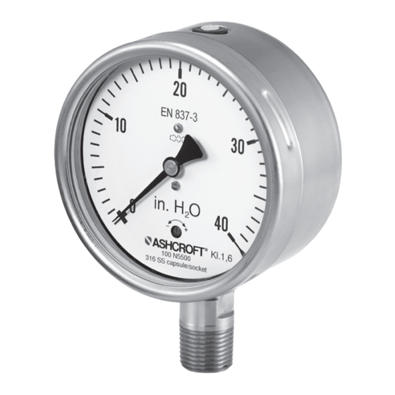
The pressure gauge is equipped with a dial face and pointer pursuant to EN 837-3, nominal size 100 mm or 160 mm.
Erläuter ung, z usätzlich ei n Hi nweis :
5.3.2 Instrument connection
The instrument connection is located on the bottom side or at the back side of the pressure gauge and is a threaded
connection.
5.3.3 Vent valve
The vent valve for the housing is located on the top side. If the nipple is pulled out, the housing is ventilated and the
pressure which has built up in the housing due to the influence of temperature is discharged. With the valve closed,
protection class IP 65 is achieved.
5.3.4 Rear wall/plug with blow-out capability
The pressure gauge has a plug capable of blowing out on the rear wall of the housing. These act as a safety feature
pursuant to EN 837-3 and simultaneously allow for temperature compensation for the housing, via a rubber
membrane.
1
2
3
4
Page 5 of 8
5
6
7
8
