- ページ 5
計測機器 Ashcroft P6500のPDF 設置およびメンテナンスの取扱説明書をオンラインで閲覧またはダウンロードできます。Ashcroft P6500 8 ページ。

5 Construction and function
5.1 Overview
1
Diaphragm
2
Rod
3
Movement
5.2 Description of function
The sensing element, the concentrically rippled diaphragm element, is clamped in place between two flanges and
charged with the medium on one side.
Under the pressure acting on it, there is an elastic displacement out of the normal position. This displacement is
proportional to the adjacent pressure. On the side of the diaphragm element facing away from the medium, a rod
picks up the displacement and transfers it to a movement mechanism.
The display of the measured value is given on a 270° scale.
5.3 Description of components
5.3.1 Scale with pointer
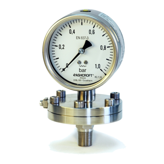
The pressure gauge is equipped with a dial face and pointer pursuant to EN 837-3, nominal size 100 mm or 160 mm.
Erläuter ung, z usätzlich ei n Hi nweis :
5.3.2 Instrument connection
The instrument connection is located on the underside of the pressure gauge and can be a threaded or flanged
connector.
5.3.3 Vent valve
The vent valve for the housing is located on the top side. If the nipple is pulled out, the housing is ventilated and the
pressure which has built up in the housing due to the influence of temperature is discharged. With the valve closed,
protection class IP 65 is achieved.
5.3.4 Rear wall/plug with blow-out capability
The pressure gauge has a plug capable of blowing out on the rear wall of the housing (Model P5500) or a rear wall
capable of blowing out (Model P6500). These act as a safety feature pursuant to EN 837-3 and simultaneously allow
for temperature compensation for the housing, via a rubber membrane.
5.4 Accessories
Please contact the manufacturer regarding special tools and accessories.
6 Transport
6.1 Safety
The pressure gauge should be protected against the effects of knocks and impacts. The device should only be
transported in the packaging provided, to protect against glass breakage. The device should only be transported in a
clean condition (free of residues of measuring media).
6.2 Transport inspection
The delivery must be checked for completeness and damage during transport. In the event of damage during
transport, the delivery must not be accepted, or only accepted subject to reservation of the scope of the damage being
recorded and, if necessary, a complaint initiated.
6.3 Storage
The pressure gauge must be stored in dry, clean conditions, within a temperature range of -40 to +70 °C, protected
against direct exposure to sunlight and protected against impact damage.
Page 5 of 8
