- ページ 3
計測機器 Ashcroft T5500のPDF インストールとメンテナンスの説明をオンラインで閲覧またはダウンロードできます。Ashcroft T5500 5 ページ。 Pressure gauges
Ashcroft T5500 にも: 設置およびメンテナンスの手順 (6 ページ)

Installation and Maintenance Instructions for
T5500 and T6500 Pressure Gauges
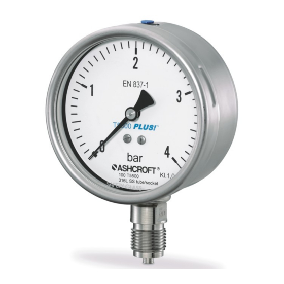
5. CONSTRUCTION AND FUNCTION
5.1 Overview
1 - Bourdon tube
2 - Socket and process
connection
3 - Movement
4 - Pointer
5 - Dial
6 - Window
7 - Bayonet ring
8 - Gasket
9 - Vent valve
10 - Case
11 - Blow-out and
compensation plug
5.2 Description of function
The sensing element, a bourdon tube (C-form or helical) that
is welded to the socket, will be exposed from inside with
pressure. Under pressure the elastic tube is deflecting against
the zero position. This deflection is proportional to the adjacent
pressure. The movement transfers the deflection to the pointer.
The display of the measured value is given on a 270° scale.
5.3 Description of components
5.3.1 Scale with pointer
The pressure gauge is equipped with a dial face and pointer
pursuant to EN 837-1, nominal size 100 mm or 160 mm
5.3.2 Instrument connection
The instrument connection is located on the bottom side
(T5500 and T6500) or at the back side (T5500) of the pressure
gauge and is a threaded connection.
5.3.3 Vent valve
The vent valve for the housing is located on the top side. If the
nipple is pulled out, the housing is ventilated and the pressure
which has built up in the housing due to the influence of
temperature is discharged. With the valve closed, protection
class IP 66 (for T6500 dry execution IP65) is achieved.
5.3.4 Rear wall/plug with blow-out capability
The pressure gauge has a plug capable of blowing out on the
rear wall of the housing (Model T5500) or a rear wall capable
of blowing out (Model T6500). These act as a safety feature
pursuant to EN 837-1 and simultaneously allow for temperature
compensation for the housing, via a rubber membrane.
5.4 Accessories
Please contact the manufacturer regarding special tools and
accessories.
6 TRANSPORT
6.1 Safety
The pressure gauge should be protected against the effects of
knocks and impacts. The device should only be transported in
the packaging provided, to protect against glass breakage. The
device should only be transported in a clean condition (free of
residues of measuring media).
© Ashcroft Inc. 2018, 250 East Main Street, Stratford, CT 06614-5145, USA, Tel: 203-378-8281, Fax: 203-385-0357, www.ashcroft.com
All sales subject to standard terms and conditions of sale. T5500-6500_gauge_im_RevB_(008-10263)_01-02-19
6.2 Transport inspection
The delivery must be checked for completeness and damage
during transport. In the event of damage during transport, the
delivery must not be accepted, or only accepted subject to
reservation of the scope of the damage being recorded and, if
necessary, a complaint initiated.
6.3 Storage
The pressure gauge must be stored in dry, clean conditions,
within a temperature range of -40 to +70 °C, protected against
direct exposure to sunlight and protected against impact
damage.
7 ASSEMBLY/INSTALLATION
7.1 Safety
To ensure safe working during installation and servicing,
suitable shut-off valves must be installed in the plant (see 5.4
Accessories), enabling the device:
• To be depressurized or taken out of operation;
• To be disconnected from the mains supply for repair or
checks within the relevant plant;
• Or to enable function tests of the device to be performed "on
site".
During the works to mount/install the gauge, the plant must be
protected against being switched back on.
7.2 Preparations (requirements for the installation location)
• A check on suitability of the device for the medium to be
measured, the scope of the measurement range and of the
protection against special conditions such as vibrations,
pulsations and pressure spikes.
• A bracket must be installed to support the pressure gauge if
the metering pipe is not able to provide adequate support.
• Devices with a blow-out require a minimum spacing to the
rear (20 mm).
• The installation location should be chosen such that the
work-spaces for operating personnel are not located to the
rear of the pressure gauge.
7.3 Mounting/Installation
7.3.1 Process connection
As standard, the device is equipped for pipework mounting
with a pressure connection shank pursuant to DIN EN 837-1.
The device is calibrated ex works for vertical installation.
• Connection to be undertaken by authorized and qualified
specialist staff only.
• Use only with the mechanical process connection provided
– regarding the configuration, see order code on the device
type label, with a matching threaded seal.
• When connecting the device, the pipes must be depressurized.
• The pressure metering pipe must be laid inclined in such
a way that, for example, for measurements of fluids no air
3
