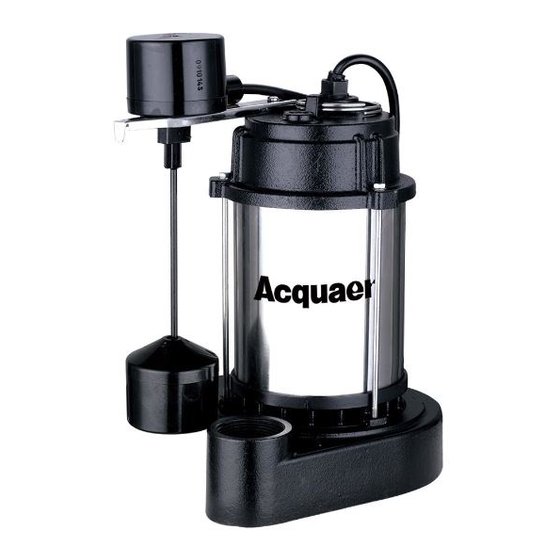
WARNING: Always use handle to lift pump. Never use power cord to lift pump. To avoid skin
burns, unplug and allow time for the pump to cool after periods of extended use.
Estimated Assembly Time (New installation): 30 minutes (or longer if installing new sump pit).
Materials Required for Assembly (not included):
Flexible connector, Check valve, PVC pipe, PVC elbow, Thread Tape
PVC Purple Primer, and PVC Cement
Tools Required for Assembly (not included):
Wrench, Phillips screwdriver
1.
Minimum sump size:12" (305mm) diameter by 12" (305mm)
depth for vertical switch models; 18" (457mm) diameter by
18" (457mm) depth for tethered switch models.
Construct the sump pit of tile, concrete, steel, or plastic; it must
meet local codes.
Make certain that no clay, earth, sand, or gravel are in the sump
(they will clog the pump).Keep the pump inlet screen clear.
2.
Install the discharge plumbing and a check valve using Teflon
tape-NOT pipe joint cement. Install the check valve in the
vertical discharge pipe to prevent flow backwards through the
pump when it shuts off. If the check valve does not have a 1/8'
anti-airlock hole, drill one in the discharge pipe just below the
valve. Be sure to install the check valve so that the flow will be
away from the pump (an arrow on the valve side will show the
flow direction).
Tighten the pipe into the pump (hand tight + 1-1/2 turns).
To prevent air locking the pump (a restriction of, or complete
stoppage of liquid flow caused by gas trapped in a high point
of a liquid-filled pipe system), drill a 1/8" (3.2mm) hole in the
discharge pipe just above where it screws into the pump
discharge. Install the check valve above this hole, but keep it
asclose to the pump as possible. Be sure the hole is below the
waterline and below the check valve.
To reduce noise and vibration cut the discharge pipe near the pump and fasten a short length of rubber
hose (1-7/8" (48mm) I.D., e.g. radiator hose) into it with hose clamps.
PREPARATION
INSTALLATION INSTRUCTIONS
1
2
'
