- ページ 6
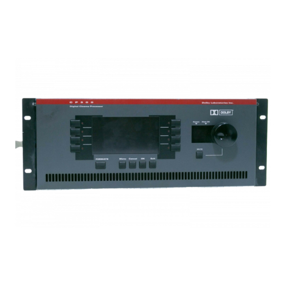
プロセッサー Dolby Laboratories CP500のPDF 参考図表をオンラインで閲覧またはダウンロードできます。Dolby Laboratories CP500 19 ページ。 Digital remote controller
Dolby Laboratories CP500 にも: ユーザーマニュアル (8 ページ)

BACKPLANE CONNECTORS / REFERENCE DIAGRAMS
CP500 Backplane Connector Pin Assignments
1. Automation Connector:
2. Serial Data Connector:
3. Motor Start Connector:
Pin
Number
1
SK1 Format Select Input
2
SK2 Format Select Input
3
SK3 Format Select Input
4
SK4 Format Select Input
5
SK5 Format Select Input
6
SK6 Format Select Input
7
SK7 Format Select Input
8
SK8 Format Select Input/or
STEP (in Automation Sequential mode)
9
Mute On/Off Input
18
Format Status Bit 0
19
Format Status Bit 1
20
Format Status Bit 2
25
Projector Status Output
12
Signal Ground
Pin
Number
1
N/C
2
Transmitted Data
3
Received Data
4
Looped back to pin 6
5
Signal Ground
6
Looped back to pin 4
7
Looped back to pin 8
8
Looped back to pin 7
9
N/C
Pin
Number
1
Motor Start Relay, Proj 1
2
Proj 1 Changeover, pulsed contacts
3
Changeover relay, closed selects Proj 2
4
Proj 2 Changeover, pulsed contacts
5
Ground
6
N/C
7
N/C
8
N/C
9
Motor Start Relay, Proj 2
Function
Signal Name
Signal Name
APPENDIX C
