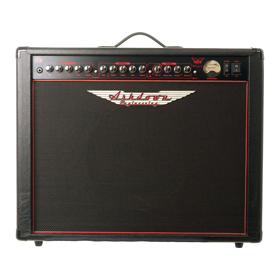
- ページ 6
楽器アンプ Ashdown Fallen Angel 40のPDF 取扱説明書をオンラインで閲覧またはダウンロードできます。Ashdown Fallen Angel 40 9 ページ。

Fro nt/ Rear Panel Facilities
FALLEN ANGEL 40, 60, 180
MASTER 1/MASTER 2
Two selectable Master Level controls are provided for further flexibility.The push button to the side of
these can be used to switch between Master 1 and Master 2. If you are using the footswitch then leave this
front panel push button in its OUT position.This is a very useful facility which allows instant switching
between two pre-set volume levels on either channel. LEDs at the top right of each control indicate which
is active.
VU METER
The VU meter indicates output power level.
STANDBY AND POWER SWITCH
Always make sure the Standby switch is in its OFF position before activating the main Power switch. Allow
the amplifier to warm up for at least 1 minute before setting the Standby to ON.
Following this procedure every time you use the amplifier will prolong the life of the tubes. Always allow
the tubes to cool down well before transporting the amplifier otherwise damage to the tubes can easily
result.
REAR PANEL FACILITIES
FUSED MAINS INLET SOCKET
This is for connection to the mains supply using supplied cable. Always use a mains outlet that has an
earth/ground connection for safety. Never remove or replace the plug on the supplied cable. Always replace
the fuse with the same type and rating as stipulated on the rear panel adjacent to the mains inlet socket.
FOOTSWITCH SOCKETS (180 Head)
There are 3 footswitch sockets provided on this amplifier. For any of these footswitch sockets to operate,
it is essential that the corresponding front panel push buttons are in the OUT position.The first of these
sockets is a mono jack for connection of the supplied 4-way footswitch. Always connect this prior to
turning on the power to the amplifier as footswitch power is derived from the amplifier.The next 2
footswitch sockets are both stereo sockets and use a standard 2-way, push on/push off type footswitches
for their operation.These may be used as an alternative to the dedicated 4-way footswitch supplied.
FOOTSWITCH SOCKETS (40 & 60 Combos, 60 Head)
There are 2 footswitch sockets provided on this amplifier.There is a mono jack socket for connecting a
suitable footswitch to allow switching between MASTER 1 & MASTER 2 volume controls.There is also a
stereo jack socket for connecting a double footswitch to allow switching between Channel 1 & Channel 2
and also for switching in the Gain Boost for Channel 2.
EFFECTS LOOPS (180 Head)
There are 2 Effects Loops provided on this amplifier. Each has two jack sockets for Effects Send & Effects
Return signals; the Effects return socket also has an Effects Return Level control associated with it for
adjusting the level of the returned signal.There is a single push button for dedicating these Effects Loops as
either Serial (where the signal path through the amplifier is broken by the effects loop) or Parallel (where
Rear Panel Facilities
FALLEN ANGEL 40, 60, 180
the effects return signal is in parallel with the signal through the amplifier). Use the 4 front panel push
buttons for assigning either of the 2 Effects Loops to Channel 1, Channel 2 or both.
N.B. Switching the effects loop IN (in Serial mode) when there are no effects connected will MUTE the amplifier as
there will be no signal returned to either Effects Return socket.
EFFECTS LOOP (40 & 60 Combos, 60 Head)
The Effects Loop on these amplifiers is a Serial loop.This has two jack sockets for Effects Send & Effects
Return signals; the Effects return socket also has an Effects Return Level control associated with it for
adjusting the level of the returned signal.
SPEAKER OUTPUT SOCKETS & IMPEDANCE SELECTOR (180 Head)
There are 3 speaker output sockets provided.The one on the far right is fixed at 16 Ohms should be used
if you are driving just one 4 x 12 cabinet (16 Ohms).The other two sockets are connected in parallel with
the IMPEDANCE SELECT switch controlling their combined impedance. Follow the scheme printed on the
back panel adjacent to these sockets for the correct impedance to use for various speaker combinations.
WARNING – Do not use open back cabinets with this amplifier as the low-end power that the amplifier produces
will cause the cones of the speakers to be damaged. Never run the amplifier without a speaker connected as this
will damage the output transformer.
SPEAKER OUTPUT SOCKETS & IMPEDANCE SELECTOR (40 & 60 Combos, 60 Head)
There are 3 speaker output sockets provided.The one on the far right is fixed at 16 Ohms and should be
used if you are driving just one 4 x 12 cabinet (16 Ohms).The other two sockets are connected in parallel
with the IMPEDANCE SELECT switch controlling their combined impedance.
INTERNAL SPEAKER 8 OHMS
This is the socket for connection to the internal 8 Ohm speaker.The impedance select switch should be
set to 8 Ohms for use with the internal speaker only (as indicated by the graphics).
EXTERNAL SPEAKER 8 OHMS
This is an external speaker socket for connecting to an 8 Ohms speaker such as a 2 x 12 cabinet (normally
8 Ohms).This socket is in parallel with the internal speaker socket, so if an external 8 Ohms speaker is
used with the internal speaker still connected then the impedance select switch will need to be set to 4
Ohms (as indicated by the graphics).
WARNING - Never run the amplifier without a speaker connected as this will damage the output transformer.
