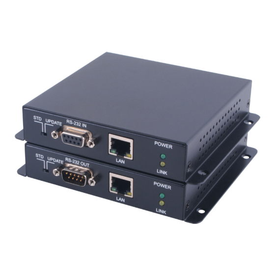
6.2 Receiver Front and Rear Panels
Front
IR2
BLASTER
IR1
EXTENDER
1
2
IR2 BLASTER: Connect to the supplied IR Blaster cable for IR signal
1
transmission. Place the IR Blaster in direct line-of-sight of the
equipment to be controlled.
IR1 EXTENDER: Connect to the supplied IR Extender cables for IR
2
signal reception. Ensure that remote being used is within the direct
line-of-sight of the IR Extender.
3
CAT5e/6/7: Connect to the Transmitter unit with a single CAT5e/6/7
cable for transmission of all data signals.
HDMI OUT: Connect to a HDMI equipped TV/monitor for display of
4
the HDMI input source signal.
STD/UPDATE Switch: This switch is reserved for factory use only.
5
RS-232 OUT: Connect to the device that is to be controlled (via
6
D-Sub 9-pin female cable) by RS-232 commands.
LAN: Connect to a PC or Laptop to utilize the Internet or network
7
function.
8
POWER LED: This LED will illuminate when the device is connected
to a power supply.
LINK LED: This LED will illuminate when both Transmitter and Receiver
9
are connected through CAT cable. When it blinks regularly it states
the Receiver is NOT sending signal but the Transmitter and Receiver
are linked and if it blinks irregularly it states an error has occurred.
HDMI OUT
3
4
Rear
RS-232 OUT
STD UPDATE
5
6
POWER
LINK
7
8 9
4
