計測機器 DOLD IP 5883のPDF 設置 / 監視技術をオンラインで閲覧またはダウンロードできます。DOLD IP 5883 6 ページ。 Varimeter rcm

Installation / Monitoring Technique
VARIMETER RCM
Residual Current Monitor, Type B for AC and DC Systems
IP 5883
IP 5883
Product Description
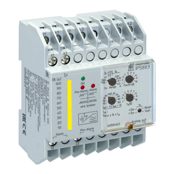
The AC/DC sensitive residual current monitor IP 5883 allows an early de-
tection of insulation faults and detects differential currents with AC as well
as DC components in grounded voltage systems (type B). The measure-
ment takes place via an external current transformer.
Contrary to an RCD the residual current monitor IP 5883 does not dis-
connect the mains when detecting a fault but only indicates it. Besides the
easy to read LED chain indicating the actual current several LEDs display
operation, pre-alarm and alarm. The 4 measuring ranges cover 10 to 3 A.
Additional features are broken wire detection, test function and adjustable
pre-alarm.
The residual current monitor IP 5883 provides early information for preci-
se and cost effective maintenance before the plant stops.
Circuit Diagrams
A1
i1
k1
i2
k2
A2
(+)
X1
X2
A1
A2
X1
X2
i1
k1
i2
k2
12
I F
11
Alarm
14
0...10V
22
U+ U-
21
Pre - Alarm
24
12
22
14
11
24
21
U+
U-
M9142_b
Connection Terminals
Terminal designation
A1, A2
i1, k1, i2, k2
X1, X2
11, 12, 14
21, 22, 24
U+, U-
1)
de-energized on trip via bridge
All Technical Data in this list relate to the state at the moment of edition. We reserve the rigth for
technical improvements and changes at any time.
ND 5018/035
ND 5018/030
Signal description
Auxiliary voltage U
H
Connection of an external
residual current transformer
Parameterization input
energized or de-energized on trip
Contacts alarm signal
Contacts pre-alarm signal
Analogue output (option)
Translation
of the original instructions
Your Advantage
• Preventive fire and system protection
• Increasing the availability of plants by early fault detection
• Universal usage at AC/DC mains
Features
• According to IEC/EN 62020, VDE 0663
• For AC and DC systems Type B, according to IEC/TR 60755
• To detect earth faults in grounded voltage systems
• 4 Setting Ranges from 10 mA to 3 A
• Manual reset, with pre-warning
• As option pre warning without auto reset
• With adjustable pre-warning
• With adjustable switching delay
• Energized or de-energized on trip
• LED indicator for operation, prewarning and alarm
• LED-chain indicates fault current
• Analogue output
• With test function
• Broken wire detection
• Removable cover
• DIN rail or screw mounting
• 70 mm width
Approvals and Markings
Application
• Monitoring of DC systems and AC systems up to 250 Hz
• For industrial and railway applications
Indicators
Green LED "ON":
On, when auxiliary supply connected
Red LED "pre alarm":
Flashes during time delay, on, when pre-alarm
active
Red LED "alarm":
Flashes during time delay, on, when alarm active
Both red LEDs:
Flashing on broken wire or extremely high input
signal
Yellow LEDs:
LED chain indicates fault current in % of adjusted
alarm value
Notes
The devices measure AC and DC current (AC/DC sensitive).Due to the
measuring prinziple they are also influenced by magnetic fields next to
current transformer.
When planning equipment with AC/DC sensitive residual current moni-
tors, components that create magnetic fields as contactors, transformers
etc., should not be placed near to the current transformer. If an influence
cannot be avoided, turning the transformer 90° could reduce the influence.
1)
1
11.01.21 en / 335A
