- ページ 6
録音機器 Cloud DCM-1のPDF マニュアルをオンラインで閲覧またはダウンロードできます。Cloud DCM-1 7 ページ。 Digitally controlled zone mixers
Architect's and Engineer's Specification
The Zone Mixer's audio signal paths shall be fully analogue in design;
there shall be a simple menu/display system on the front panel for
accessing all system controls and configuration options. It shall be
possible to access all control functions without the use of any external
computers or software. A PC-compatible software application shall
be available; this shall interface with the Zone Mixer via an RS232
connection and shall provide an alternative method of accessing all
control and configuration options.
Two versions of the Zone Mixer shall be available; these shall be identical
in terms of their audio functions. One shall include an standard RJ45
Ethernet interface and internal web server; on this version it shall be
possible to access main control functions from a standard web browser
on devices connected to the same network as the Zone Mixer.
The Zone Mixer shall have 8 stereo line channels, 4 microphone inputs
and a paging mic input. Line inputs shall be on RCA jacks; one shall also
be available as a balanced input on Euroblock connectors; four shall
also have RJ45 sockets providing balanced inputs for the connection
of optional balanced or unbalanced stereo external connection
modules. The microphone inputs shall be balanced on RJ45 sockets for
connection of optional external modules. The Line Inputs shall each
have level trim adjustment available via the menu system. The remote
modules shall be available in a range of sizes and finishes.
The Zone outputs shall be balanced on Euroblock connectors. At
least two shall be stereo, the remainder mono. It shall be possible to
adjust the following parameters for each Zone output: Level, Maximum
and Minimum Levels; EQ (3-bands). It shall be possible to route any
microphone or line input to any Zone output without restriction,
and to adjust each Zone output level independently. It also shall be
possible to make one or more line Inputs unavailable to any Zone
without restriction. It shall also be possible to define up to 4 Groups
of Zones; enabling/disabling Groups shall be possible without entering
a password. It shall be possible to assign alphanumeric names to all
Inputs, Zones and Groups; these will still apply after any hardware reset
operation.
An optional remote control plate with the same display as the host
unit shall be available for the Zone Mixer. The plate shall be provided
with IN and OUT sockets to permit series interconnection of up
to 100 plates. It shall be possible to configure a plate to provide the
following control functions for its assigned Zone: for immediate access
- Line Input Select and Music Level; with password entry – Zone EQ
(3 bands). The plates shall be available in a range of styles and finishes.
The Zone Mixer shall interface directly with Cloud PM Series paging
microphones and/or third-party paging microphones employing short-
to-ground zone access. The input for a third-party Paging Mic shall be
dedicated, and on a Euroblock connector; routing this to any/all Zones
will be by contact closure at a separate Euroblock connector. Both
Paging Mic inputs shall have rear panel gain controls; HF and LF EQ
controls shall also be provided, effective on both inputs.
Cloud Electronics Limited
140 Staniforth Road, Sheffield, S9 3HF. England.
Telephone: +44 (0)114 244 7051 Fax: +44 (0)114 242 5462
Web: www.cloud.co.uk E-mail: [email protected]
Issue_1.0
The Zone Mixer shall have a rear panel paging level adjustment for
each Zone. The music signal in a Zone shall reduce in volume when
that Zone is being paged, and the Hold Time, Release Time and Music
Attenuation shall all be adjustable. It shall also be possible to trigger
music level reduction by Zone Selection or Paging Mic signal presence.
It shall be possible to assign per-Zone Priority status to any line or
microphone input, such that a Priority signal above a fixed threshold
overrides the current Input selection in each Zone for as long as the
Priority signal remains above the threshold. In connection with this,
the following parameters shall be adjustable: Hold Time, Release Time;
Music Attenuation (Mic Priority only).
There shall be a Music Mute Input; this will cause muting of the music
in all Zones. Muting control shall be configurable on either external
contact closure (N/O) or short-circuit removal (N/C). It shall also be
possible to assign any one line or microphone Input to remain unmuted
during Music Mute operation for Emergency system interface.
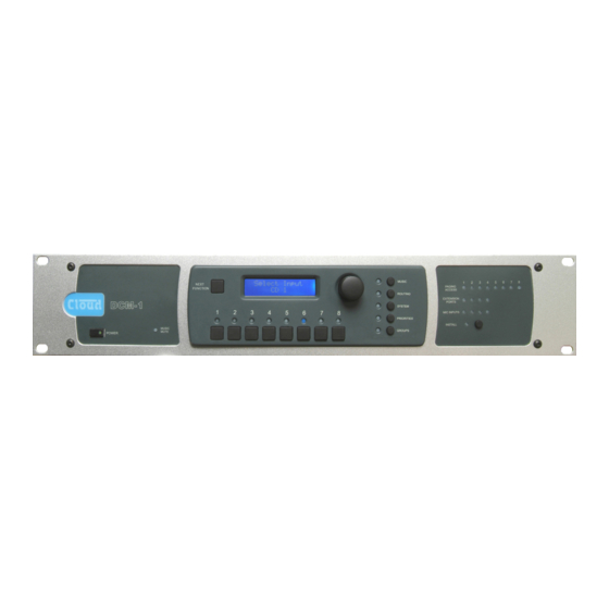
The front panel shall provide the following features: power switch,
backlit LCD display, rotary encoder with "press" function and software-
assignable push-buttons for control functions. One of the buttons
shall control the Zone Mixer's menu system. Five further buttons
shall select submenus, and another button shall activate a set of menu
options which require the entry of a password. The password shall be
redefinable by the User. The front panel shall also include various LEDs
indicating: external paging access, remote line input selection, remote
mic input selection and emergency Music Mute activity.
It shall be possible to save all current settings and reload these settings
when power is applied. Alternative power-up options shall be to load
the original factory settings or those in force at power-down, even if
they were not specifically saved.
The Zone Mixer shall include an RS232 serial port permitting remote
control of all unit functions and settings. The Ethernet-enabled version
of the Zone Mixer shall also have the ability to relay serial data from
the Ethernet port to the serial port; it shall also be possible to redefine
the function of the Paging Access connector to provide open-collector
pull-down outputs becoming active under commands received at the
RS232 or Ethernet ports.
It shall be possible to retro-fit optional loudspeaker equaliser cards
to any or all Zone outputs. Cards shall be available to optimise the
outputs for use with various popular installation loudspeakers.
The Zoner shall be built in a steel chassis for mounting in a standard
19" rack enclosure.
The Zone Mixer shall be the Cloud DCM1; the Ethernet-enabled
version shall be the Cloud DCM1e. The remote control plates shall
be the Cloud CDR-1 Series; the remote input plates the Cloud LE-1
Series (unbalanced line), Cloud BE-1 Series (balanced line) and Cloud
ME-1 Series (microphone).
Cloud Electronics USA
2065 Sidewinder Drive, Suite 200, Park City,
Utah 84060. United States of America.
Toll Free: 0855 810 0161
Web: www.cloudusa.pro E-mail: [email protected]
C l e a r l y b e t t e r s o u n d
E&OE