- ページ 13
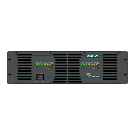
アンプ Ashly MFA-6000のPDF 取扱説明書をオンラインで閲覧またはダウンロードできます。Ashly MFA-6000 20 ページ。 Ashly audio corporation operating manual power amplifier mfa-8000, mfa-6000

Operating Manual - MFA-8000 and MFA-6000 Power Amplifier
9.3
Bridged Mono Operation
(Normal/bridging switch in, channel 1 input used, channel 1 level control used, BRIDGED output used)
10.
DESIGN THEORY
The MFA Series amplifiers are based on a dual-
monaural design with each channel being electrically and
physically identical. This type of design improves audio
performance by eliminating power supply interaction and
crosstalk. Failure of one channel will not affect the other.
Because each channel is physically independent and fully
integrated onto its own modular assembly, servicing is sim-
plified.
The output stages of the MFA amps use compli-
mentary bipolar power transistors. Bipolar transistors were
chosen for maximum power efficiency and greater output
current capacity, both of which are particularly important
in high-power, low-frequency applications. Like all other
Ashly power amps, all power and gain stages are 100%
discrete. In other words, there are no op-amps used within
the power amp's main signal path or feedback loop. This
results in an exceptionally clean and well behaved output
waveform (no glitching or ringing) in the presence of tran-
sients or clipping.
All power supply high current paths are retained
on each channel's respective PC board, keeping wiring to
a minimum. The power supply uses three DC voltage lev-
els which are switched sequentially by ultrafast MOSFETs
depending on the demands of the output voltage. This
concept is employed for greater power efficiency and to
reduce the AC power consumption.
Sophisticated power amp monitoring circuits de-
tect any abnormal conditions which may cause damage
to the amplifier or speakers. A highly accurate clip de-
tector illuminates the CLIP LED at the onset of clipping.
Further increases in signal level will activate a limiter
circuit which prevents severe overload distortion from oc-
curring. This limiter circuit illuminates the LIMIT LED
when it becomes active, where the light intensity of the
LED indicates the amount of signal attenuation.
Advanced thermal management circuitry senses
temperature at four locations in the amp and adjusts fan
speed accordingly. A THERMAL LED on each channel
indicates an above normal operating temperature. The
light intensity of this LED is an indication of the
temperature above normal. If the internal temperature
becomes excessive, the limiter circuit will attenuate the
input signal until the amplifier returns to a normal
operating range.
The amplifier's output will
automatically shut down in the event of a fault condition
such as severe overheating, shorted output, DC voltage,
or extreme high frequency energy. A PROTECT LED
indicates when one or more of these abnormal conditions
occur. Each channel's limiting, thermal, and protection
management functions are completely independent of the
other channel.
The MFA Series amplifiers are equipped with the
necessary circuitry for computer control and monitoring
as this capability becomes available in the future.
13
