- ページ 6
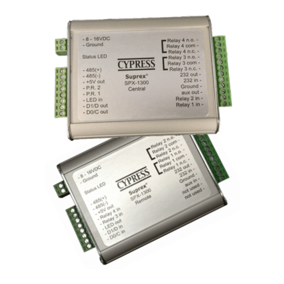
エクステンダー Cypress Suprex SPX-1300のPDF 操作マニュアルをオンラインで閲覧またはダウンロードできます。Cypress Suprex SPX-1300 16 ページ。 Reader extender
Cypress Suprex SPX-1300 にも: 操作マニュアル (17 ページ)

Actual connections will differ based on the type of format, features utilized, and equipment interface."
The following diagrams are an example of a typical installation using the Suprex 1300 and a Wiegand format
"
Reader and Access Control Panel."
1. First connect units as shown below to verify basic function and communication. This should be done in a
convenient location such as a bench top before installing units in the field. Both units can share the same power
supply if the power supply has sufficient capacity. "
" "
When Connected as shown below, both units should have the Diagnostic LED flashing Green about 2-3 flashes
per second (Rapid flashing)
8 - 16 VDC "
Power "
Supply
8 - 16 VDC "
Power "
Supply
Suprex Operation and Initial Setup
+VDC
2-8 to 16 VDC In"
1-Ground
Ground (0V)
8-485(+)"
7-485(-)
6-+5 VDC Out"
5-Prog Res 2"
4-Prog Res 1"
3-LED Input"
2-D1/Data/F2F Out"
1-D0/Clock Out"
+VDC
2-8 to 16 VDC In"
1-Ground
Ground (0V)
8-485(+)"
7-485(-)
6-+5 VDC Out"
5-RLY4 Input (5V)"
4-RLY3 Input (5V)"
3-LED Output"
2-D1/Data/F2F Input"
1-D0/CLK Input
"
"
"
"
"
"
"
"
"
"
"
"
"
"
"
"
"
"
"
"
"
"
"
"
Central Unit
"
"
*
"
"
"
1-D0/CLK Output
"
"
"
"
"
"
"
"
"
"
"
"
"
"
"
"
Remote Unit
"
*
"
"
"
"
"
"
"
12-RLY4 N.O."
11-RLY4 Com"
10-RLY4 N.C."
9-RLY3 N.O."
8-RLY3 Com"
7-RLY3 N.C."
6-RS232 Out"
5-RS232 In"
4-Ground"
3-Aux Out"
2-Relay2 Input"
1-Relay1 Input"
12-RLY2 N.O."
11-RLY2 Com"
10-RLY2 N.C."
9-RLY1 N.O."
8-RLY1 Com"
7-RLY1 N.C."
6-RS232 Out"
5-RS232 In"
4-Ground"
3-Aux In"
2-N/C"
1-N/C"
