2022/03/16 04:45
powering up the controller, you will see COM1 and COM2 after powering it up.)
The USB drivers on your computer create a virtual serial port whenever the computer is connected to
a powered-up controller. This virtual serial port operates like an RS-232 port as described below.
RS-232 Ports
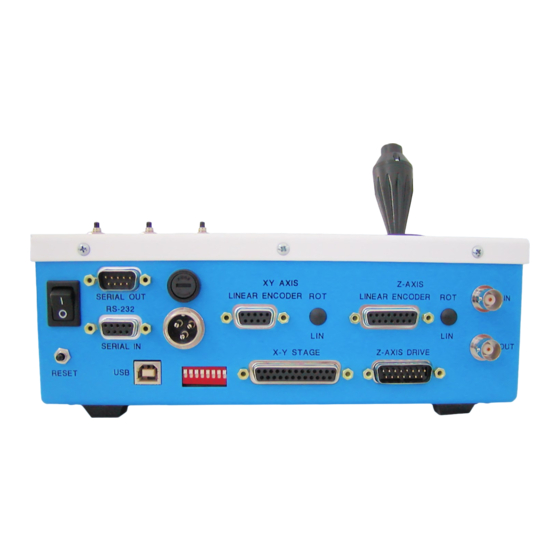
The two 9-pin RS-232 ports allow serial commands to talk to and through the MS 2000. The IN port
attaches to the PC computer via a null modem RS 232 Serial Cable to allow serial commands to
control and get information from the MS 2000. The null modem cable switches the RX and TX lines
and terminates possible PC handshaking lines allowing for asynchronous communication without
handshaking. The OUT port is controlled by a second UART on the microcontroller. As a default it is
configured as a "pass though" so serial traffic sent to the controller from the PC is echoed directly on
the OUT port. Special functions are supported that use this port for dedicated purposes (e.g. triggered
encoder reporting).
Fuse
The MS 2000 uses a 1A, 250V, fast blow, 5x20mm standard fuse.
Power Input
The MS 2000 uses a 24V 1.25A universal input, switching DC power supply. The power supply is
connected and disconnected from the circuits via the ON/OFF power switch.
X-Y Stage Connector
This DB-25 connector is used to connect the MS 2000 to the X/Y stage via a four foot cable.
Z-Axis Connector
This DB-15 connector is used to connect the MS 2000 to the Z-Axis drive assembly via a four foot
cable.
Linear Encoder Connectors
X ,Y & Z linear encoder connectors are located on the back panel. Heidenhain encoders utilize labeled
DB-15F connectors. If the encoders are cross connected, the affected axes will behave erratically.
BNC Connectors
Applied Scientific Instrumentation - https://asiimaging.com/docs/
5/18
MS2000, MFC2000 and RM2000 OPERATION
