- ページ 17
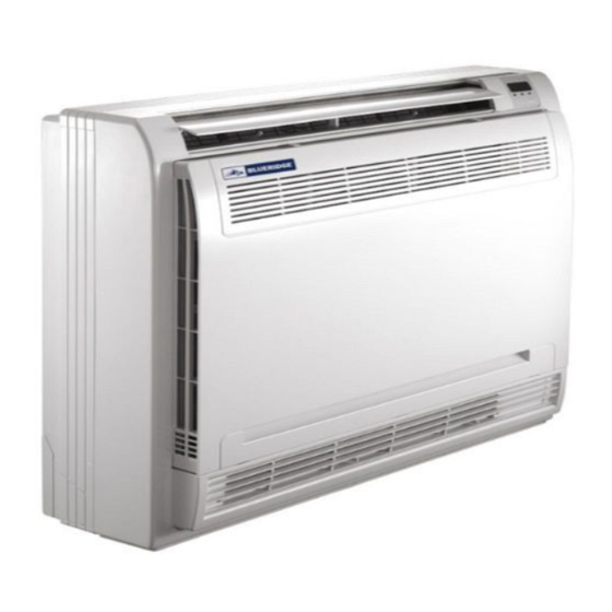
エア・ハンドラー Blueridge BM12M22CNSのPDF インストレーション・マニュアルをオンラインで閲覧またはダウンロードできます。Blueridge BM12M22CNS 20 ページ。 Low-wall air handler

Wiring
BEFORE PERFORMING ANY ELECTRICAL WORK, READ THESE REGULATIONS
1. All wiring must comply with local and national electrical codes, regulations and must be
installed by a licensed electrician.
2. All electrical connections must be made according to the Electrical Connection Diagram
located on the panels of the indoor and outdoor units.
3. If there is a serious safety issue with the power supply, stop work immediately. Explain
your reasoning to the client, and refuse to install the unit until the safety issue is properly
resolved.
4. Power voltage should be within 90-110% of rated voltage. Insufficient power supply can
cause malfunction, electrical shock, or fire.
5. Power from your panel must be on a dedicated circuit with the correct amperage breaker,
run through an approved electrical disconnect box mounted on an exterior wall near the
condenser.
6. Make sure to properly ground the air
conditioner.
7. Every wire must be firmly connected.
Loose wiring can cause the terminal
to overheat, resulting in product
malfunction and possible fire.
8. Do not let wires touch or rest against
refrigerant tubing, the compressor, or
any moving parts within the unit.
9. If the unit has an auxiliary electric heater,
it must be installed at least 40" away
from any combustible materials.
10. To avoid getting an electric shock, never
touch the electrical components soon after
the power supply has been turned off.
11. Make sure that you do not cross
your electrical wiring with your signal
wiring. This may cause distortion and
interference.
NOTE ON Electrical Disconnect
You must use a dedicated circuit, with an
approved electrical disconnect switch to
provide power at the outside unit. The inside
unit wires connect to the outside unit, not to
power circuits indoors.
Revised 5/14/2020
Disconnect switch
(purchased seperately)
Outdoor unit power wires Indoor & Outdoor
Outdoor unit
NOTE: This diagram is for explanation purposes
only. Your machine may be slightly different.
WARNING
BEFORE PERFORMING ANY ELECTRICAL OR
WIRING WORK, TURN OFF THE MAIN POWER
TO THE SYSTEM.
7
connective wires
(purchased seperately)
Indoor unit
Page 17
