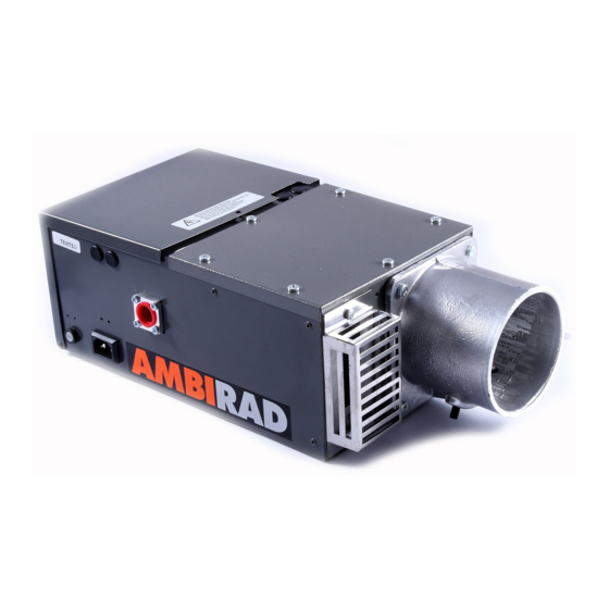
Ambirad ARE40 U 설치 및 서비스 매뉴얼 - 페이지 6
{카테고리_이름} Ambirad ARE40 U에 대한 설치 및 서비스 매뉴얼을 온라인으로 검색하거나 PDF를 다운로드하세요. Ambirad ARE40 U 20 페이지. Gas fired radiant tube heaters

- 1. Table of Contents
- 2. AR and ARE Series Gas Fired
- 3. Gas Connection
- 4. Standards
- 5. Assembly Instructions
- 6. Fitting Reflectors and End Caps
- 7. Burner/Fan/Damper Assembly
- 8. AR and ARE Series Double Linear
- 9. HB and DL Damper Settings
- 9. Installation – Suggested Methods
- 9. Of Heater Suspension
- 10. Flue Connection
- 11. Commissioning for Individually
- 12. Routine Service
- 13. Trouble Shooting Checklist
- 14. User Instructions for Ambi-Rad
5 Assembly instructions
For assembly drawings and details on specific heaters please refer to the following data sheets.
AR series
AR13 UT/AR13 HB
AR22 UT/AR22 HB
AR35 & 40 UT/AR35 & 40 HB
AR45 & 50 UT/AR45 & 50 HB
AR13 SL/DL HB (22ft)
AR22 SL/DL HB (24ft)
AR22 SL/DL HB (27ft)
AR22 SL/DL HB (32ft)
AR22 SL/DL HB (36ft)
AR35 SL/DL HB (33ft)
AR35 SL/DL HB (42ft)
AR35 SL/DL HB (50ft)
AR40 SL/DL HB (42ft)
AR40 SL/DL HB (50ft)
AR45 SL HB (50ft)
AR45 SL HB (60ft)
AR50 SL HB (50ft)
AR50 SL HB (60ft)
ARE13 UT/ARE13 HB
ARE22 UT/ARE22 HB
ARE35 & 40 UT/ARE 35 & 40 HB
ARE45 & 50 UT/ARE 45 & 50 HB
ARE13 SL/DL (22ft)
ARE22 SL/DL HB (27ft)
ARE35 SL/DL HB (42ft)
ARE40 SL/DL HB (42ft)
ARE45 SL HB (50ft)
ARE45 SL HB (60ft)
ARE50 SL HB (50ft)
ARE50 SL HB (60ft)
6 Health and safety
Ambi-Rad Limited cannot be responsible for
ensuring that all site safety procedures are
adhered to during assembly and installation.
Sole liability rests with the installer.
7 Fixing tubes and brackets
'U' tube
General assembly instruction for the;
AR UT/HB
Support radiant tubes on blocks, trestles etc,
ensuring the internal welded seam of the
tube is facing downwards. Ensure tubes are
clear internally.
6
Data sheet reference number
GB/AR/063/0800
GB/AR/064/0103
GB/AR/065/0103
GB/AR/066/0103
GB/AR/068/0901
GB/AR/069/0901
GB/AR/083/0603
GB/AR/084/0901
GB/AR/087/0901
GB/AR/070/0901
GB/AR/089/0103
GB/AR/093/0103
GB/AR/090/0103
GB/AR/094/0103
GB/AR/096/0103
GB/AR/097/0103
GB/AR/098/0103
GB/AR/092/0103
GB/ARE/071/0800
GB/ARE/072/0800
GB/ARE/073/0800
GB/ARE/074/0800
GB/ARE/075/0901
GB/ARE/076/0901
GB/ARE/077/0901
GB/ARE/078/0901
GB/ARE/099/0901
GB/ARE/100/0901
GB/ARE/101/0901
GB/ARE/091/0901
Push one turbulator into each tube flush
with the end adjacent to the return bend
(opposite end to the burner and fan).
Turbulators are not supplied with any
heaters in the
13 range.
AR
Slip return bend completely onto tubes with
the clamping bolts facing upwards. Tighten
securely.
Slip the suspension brackets onto the tube
assembly.
Position the brackets as shown on relevant
data sheet.
AR13 UT/AR13 HB
The AR13 heater has one suspension
bracket fitted with reflector locating tabs.
This bracket must be located nearest the
burner/open end of the tube assembly.
AR22 UT/AR22 HB
Fit additional centre support bracket onto the
tube assembly. 'U' bolts for the centre
support bracket and suspension brackets are
not interchangeable.
AR35 UT/AR35 HB and AR40 UT/AR40 HB
Identify the difference between the two
radiant tubes. The burner tube comprises of
half mild steel and half stainless steel. The
stainless steel is labelled 'burner end only'
and must be installed adjacent to the burner.
There are two types of suspension brackets
Type 'A' and Type 'B', one of the Type 'A'
brackets must be fitted with one standard 'U'
bolt and one extra long threaded 'U' bolt. The
extra long threaded 'U' bolt with 'stop-nuts'
to be located on the stainless steel firing
tube as indicated and bolted into position.
Clearance of 3mm must be provided around
the tube to allow for thermal expansion. (See
Fig 4).
AR45 UT/AR45 HB and AR50 UT/AR50 HB
Identify the difference between the two
radiant tubes. The stainless steel burner tube
is labelled and weighs less than the return
tube. The stainless steel tube must be located
on the firing leg only. Join short tube to long
tube with swaged joint. One of the Type 'B'
brackets must be fitted with one standard 'U'
bolt and one extra long threaded 'U' bolt
with 'stop-nuts' to be located on the
stainless steel firing tube as indicated and
bolted into position.
Clearance of 3mm must be provided around
the tube to allow for thermal expansion. (See
Fig 4).
The above assembly instructions apply
to ARE UT/HB series of heaters. However,
turbulators are not supplied.
Linear
General assembly instructions for AR SL/HB.
We advise that the tube assembly be built
in the roof space where the heater will
eventually be situated. This is due to the
overall length of the heater, which could
be too large for floor assembly.
Referring to the relevant data sheets
suspend the brackets as directed.
