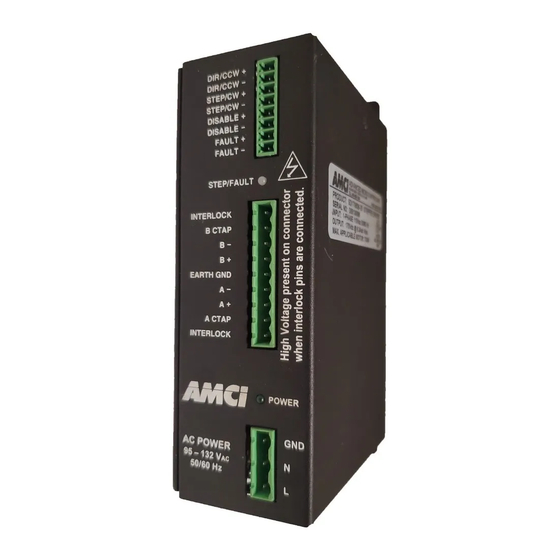
AMCI SD17060B-03 사용자 설명서 - 페이지 9
{카테고리_이름} AMCI SD17060B-03에 대한 사용자 설명서을 온라인으로 검색하거나 PDF를 다운로드하세요. AMCI SD17060B-03 20 페이지. Stepper drives

The SD17060B is configured by DIP switches on the top of the driver. The factory default setting has all
switches in their off (0) position except for SB2-1. (CurrentLoop Gain = 1) All switch setting are latched.
You must cycle power to the driver before changes take effect.
Note on Idle Current Reduction
The SD17060B controls the
RMS current through the motor.
Therefore it can momentarily
put 1.4 times the motor's rated
current through the windings
safely. If you choose a setting
of No Reduction, the
SD17060B will revert to peak
current control when the motor
is not turning. This feature pro-
tects the motor from damage.
You will not see a reduction in
holding torque.
Disable Input
You can program the Disable Input's
active state. When Active High, you
must apply power to the input to disable
the driver. When Active Low, you must
apply power to the input to enable the
driver. If you are not using the input, set
this switch to Active High and the driver
will operate as you expect. When the
Disable Input is active, the SD17060B
removes power from the motor and stops
accepting indexer pulses. Over-temp and
Over-current faults are cleared when the
driver transitions from a Disabled state.
Anti-Resonance
Allows the SD17060B to compensate for
back-EMF generated by the motor. It
should be left enabled for most applica-
tions. Disable only if you are sure you do
not want this feature or under the advice of
AMCI tech support.
Current Loop Gain
This setting allows you to compensate for
variations in motor properties which will give you smoother motion and better positional
accuracy. See the
Self-Test Mode
Self-Test mode is controlled by the switch SB4-1. If you change the state of this switch
while power is applied to the SD17060B, the driver will respond by rotating the attached
motor clockwise at 60 RPM with a resolution of 50,000 steps per turn. Note that changing
this switch does not alter the current supplied to the motor. All switch settings are read and
latched on power up. However, you must return this switch to its correct setting for normal
operation before cycling power or resetting the SD17060B.
20 Gear Drive, Plymouth Ind. Park, Terryville, CT 06786
Tel: (860) 585-1254 Fax: (860) 584-1973 http://www.amci.com
SWITCH SETTINGS
ON
SWITCH
SETTINGS
PULSE TRAIN INPUT
CW/CCW
IDLE CURRENT
REDUCTION
NO REDUCTION
Setting the Current Loop Gain
SB1
SB2
DISABLE INPUT
ACTIVE STATE
ACTIVE LOW
ANTI-RESONANCE
CURRENT LOOP
GAIN
Gain = 1
Gain = 2
Gain = 3
Gain = 4
Gain = 5
Gain = 6
Gain = 7
Gain = 8
Gain = 9
Gain = 10
Gain = 11
Gain = 12
Gain = 13
Gain = 14
Gain = 15
Gain = 16
Gain = 17
Gain = 18
Gain = 19
Gain = 20
Gain = 21
Gain = 22
Gain = 23
Gain = 24
Gain = 25
Gain = 26
Gain = 27
Gain = 28
Gain = 29
Gain = 30
Gain = AutoMode
section on page 14 for more information.
SB3
SB4
SD17060B
RESOLUTION
(Steps / Revolution)
SD17060B-25
RESOLUTION
(Steps / Revolution)
1.0
1.0
1.0
1.0
1.0
1.0
1.0
1.0
1.0
1.0
1.0
1.1
1.2
1.3
1.4
1.5
1.6
1.7
1.8
1.9
2.0
2.1
2.2
2.3
2.4
2.5
2.6
2.7
2.8
2.9
3.0
3.1
3.2
3.3
3.4
3.5
3.6
3.7
3.8
3.9
4.0
4.1
4.2
4.3
4.4
4.5
4.6
4.7
4.8
4.9
5.0
5.1
5.2
5.3
5.4
5.5
5.6
5.7
5.8
5.9
6.0
6.1
6.2
6.3
9
