Coachsound TourMaster-Lite TML2500 사용자 설명서 - 페이지 4
{카테고리_이름} Coachsound TourMaster-Lite TML2500에 대한 사용자 설명서을 온라인으로 검색하거나 PDF를 다운로드하세요. Coachsound TourMaster-Lite TML2500 15 페이지. Two channel audio server
Coachsound TourMaster-Lite TML2500에 대해서도 마찬가지입니다: 설치 매뉴얼 (11 페이지)
TourMaster-Lite User Manual v 4.0
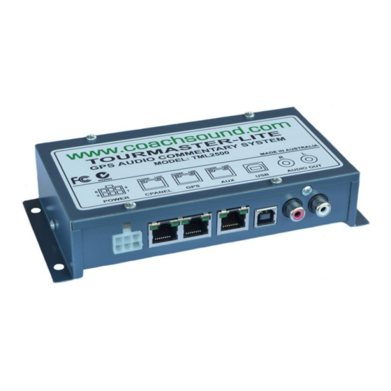
1.1 HEAD UNIT – ELECTRICAL PORTS AND CONNECTIONS DIAGRAM
The purpose of the TourMaster-Lite System Head Unit is to receive a GPS signal and play appropriate
commentary over the existing audio system.
Head Unit Port and Connections Diagram
1.2 POWER CONNECTION
This connection is the main power connection for the system. The system can operate from 10V to 30V (12V to
24V nominal).
•
10V-30V, GROUND - POWER SUPPLY:
These are the power supply 2 connections to the system. Power should be connected to the ignition
side of the key (so power does not disconnect during engine cranking). To prevent flat batteries, the
system should be powered after any isolator switches so the system loses power when the isolator is
turned off. The system is internally over-current protected but external fuse protection is also
recommended for additional safety:
o
Recommended external fuse protection: 3 Amp
o
Maximum current (operational – ON via control panel): 1 Amp
o
Maximum current (shutdown – OFF via control panel): 100mA
•
PCON1, PCON2 - REMOTE POWER CONTROL:
If a control panel is not used with the system, shorting these two connections together via a switch
offer an alternative method of powering up the system remotely.
Figure 1 Head Unit Ports / Connections
Figure 2 Power Connection
2