American Standard Tropic 7038.801 설치 지침 매뉴얼
{카테고리_이름} American Standard Tropic 7038.801에 대한 설치 지침 매뉴얼을 온라인으로 검색하거나 PDF를 다운로드하세요. American Standard Tropic 7038.801 6 페이지. Spread lavatory faucet with speed connect drain
American Standard Tropic 7038.801에 대해서도 마찬가지입니다: 설치 지침 매뉴얼 (6 페이지)
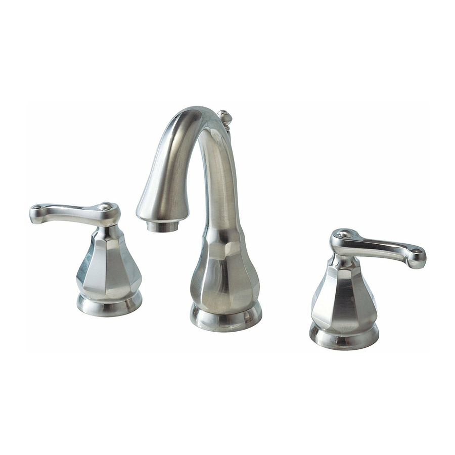
TROPIC
Spread Lavatory Faucet with
Speed Connect™ Drain
Congratulations on purchasing your American Standard
faucet with Speed Connect drain, a feature found only on
American Standard faucets.
Speed Connect™ Drain*
• Fewer parts, installs in less time
• Never needs adjustment
• Guaranteed to seal properly the first time, every time.
*Your new American Standard faucet is designed to work only with the Speed Connect drain.
To ensure that your installation proceeds smoothly-please read these instructions carefully before you begin.
Recommended tools
Screwdriver
1
INSTALL SPOUT
Insert SPOUT (1) and CABLE CONNECTOR (14) through center hole, making sure
the SPOUT ESCUTCHEON (2) and SEAL WASHER (3) are properly seated.
Assemble RUBBER WASHER (4), BRASS WASHER (5) and LOCKNUT (6) onto SPOUT
SHANK (7) from under side of sink . Make sure SPOUT (1) is centered in the mounting
hole and the slot in the BRASS WASHER (5) faces toward the rear of the sink.
Tighten LOCKNUT (6) firmly. Fig. A.
1A
INSTALL VALVE BODY
Place RUBBER RING (9) into ADAPTER (10).
Install LOCKNUT (11) and RUBBER WASHER (12) onto VALVE BODY (13).
From under side of mounting surface, install VALVE BODY (13) through valve
mounting holes. Threads of VALVE BODY (13) should extent at least 5/16
of a inch above mounting surface top. Fig. B. Thread ADAPTER (10)
onto VALVE BODY (13) until snug against internal stop. If necessary, adjust
LOCKNUT (11).
Tighten LOCKNUT (11) with WRENCH (8) (supplied) to secure VALVE
BODY (13). Repeat above steps for opposite VALVE BODY (13A).
10
9
5/16'' MIN.
Fig. B.
8
Channel Locks
Turn off hot and cold water
CAUTION
supplies before beginning.
MOUNTING
SURFACE
12
11
13
Installation
Instructions
7038.801
Adjustable Wrench
1
10
9
12
11
13
1
Certified to comply with ANSI A112.18.1
M 9 6 8 8 9 2 R e v . 1 . 1
Tubing Cutter
Fig. A.
2
3
SLOT
13a
1
7
4
5
6
14