AMERITRON RCS-12 사용 설명서 - 페이지 5
{카테고리_이름} AMERITRON RCS-12에 대한 사용 설명서을 온라인으로 검색하거나 PDF를 다운로드하세요. AMERITRON RCS-12 16 페이지. Automatic antenna switch

Ameritron RCS-12 Instruction Manual
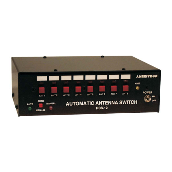
RCS-12 Front Panel
ANT 1
ANT 2
AUTO
AUTO
MANUAL
MANUAL
1. Power Switch:
2. Transmit Indicator:
4. Auto/Manual Switch:
5. ANT 1 – ANT 8 Switches:
6. ANT 1 – ANT 8 LED:
RCS-12 Rear Panel
GND
116 Willow Rd.
Starkville, MS USA
RADIO
AMP
KEY
KEY
POWER
IN
IN
12-30 VDC
+
1. Power:
2.5x5.5mm coaxial jack accepts +12V to +30V Volts DC
2. Radio Key In:
3. Amp Key Out:
4. Radio Input:
5. Aux. Input:
6. Aux. Output:
7. Station Ground:
8. Relay Output:
ANT 3
ANT 4
AUTOMATIC ANTENNA SWITCH
Front Panel Description
Unit Power Switch.
Yellow LED Illuminates While Transmitting.
Automatic (Green LED)/ Manual (Red LED).
Selects Desired Antenna.
Illuminates Showing Selected Antenna and status
RADIO
AMP
INPUTS
KEY
OUT
Rear Panel Description
Female Phono Jack, Radio Key Line from Radio
Female Phono Jack, Amp Key Line to Amp
DB-9 Male, Band Data Inputs/Radio Key from Transceiver
DB-9 Female, Push-Button or Computer Control
DB-9 Female, 1 of 8 Data Out and Transmit Flag
Ground Lug for Connection to Station Ground
8-Pin Din Jack, Output to Tower-Mounted Relay Box
ANT 5
ANT 6
ANT 7
RCS-12
AUX
INPUTS
3
Automatic Antenna Switch
XMIT
POWER
TO
AUX
RELAY BOX
1 OF 8
OUTPUTS
OUTPUT
ON
OFF
