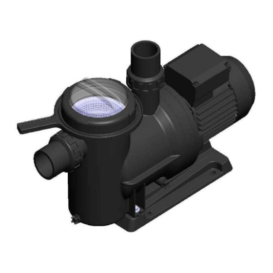
Astralpool COLUSA 70582 설치 및 유지 관리 매뉴얼 - 페이지 6
{카테고리_이름} Astralpool COLUSA 70582에 대한 설치 및 유지 관리 매뉴얼을 온라인으로 검색하거나 PDF를 다운로드하세요. Astralpool COLUSA 70582 10 페이지.

3. INSTALLATION AND ASSEMBLY
GENERAL
- Our pumps may only be assembled and installed in pools or ponds that are compliant with HD 384.7.702. Should
you have any doubts, please consult your specialist.
- The pumps are fitted with a pre-filter with a basket inside to collect any large particles, as they may damage the
hydraulic part inside the pump. This pre-filter means that the pump must be assembled horizontally.
- All pumps are fitted with a foot with two holes in it to anchor it to the ground (Fig. 1).
PIPING
- The piping must be connected by gluing it to the fittings supplied with the pump; the fitting connections to the
suction and return ports on the pump are threaded and include seals to prevent water loss (Fig. 2).
- The return pipes must be fitted completely perpendicular and centred in relation to the port to be connected to
prevent the pump and the pipe from being subjected to external stress that, apart from making fitting difficult, could
break them (Fig. 2).
- The suction piping will be installed on a slight 2% slope towards the pump to avoid the formation of air pockets
(Fig. 2).
- To ensure the pump works correctly, prime the pump pre-filter until water rises up through the suction pipe (Fig.3).
LOCATION
- To improve pump performance, it should be fitted underneath the water level in the pool.
- Where a self-priming pump is to be fitted above the water level, the difference in height must be no more than 2
metres (Fig. 4), ensuring that the suction pipe is as short as possible as a long pipe would increase drainage times
and load losses in the installation.
- Make sure that the pump is safe from possible flooding and receives dry ventilation.
ELECTRICAL INSTALLATION
- The electrical installation must include a multiple separation system with contact openings of at least 3 mm.
- Only stiff wiring can be used for mains connections. Where flexible wiring is used for mains connections it must
include terminals for connection to the pump motor terminals.
- With any type of pump, 0.03 A differential protection must be fitted for electricity leakage protection (indicated on
the diagrams).
- Adjust the value of the thermal relay appropriately depending on the pump current.
For pumps with a single-phase motor:
Thermal protection must be fitted. Installation with a switch is sufficient, in line with the "Mains connections"
diagram.
A motor guard with magneto-thermal protection must be used.
The adjustment data for the thermal relay is to be used as a guideline, as the motor is already fitted with protection.
For 230 V, use a H07 RN-F3 type connection sleeve with a cable section that adapts to the power of the motor and
to the length of the cable.
For pumps with a three-phase motor:
A motor guard with magneto-thermal protection must be used.
The pump must be protected against overloads with a cut-off switch for the motor.
For voltage ranges other than 230/400V, 400/690V, connect the lowest voltage at Δ and the highest at Υ.
Installation and General Maintenance Manual
- POOL PUMPS
5
