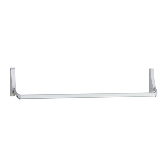
Dor-O-Matic 1992 설치 지침 매뉴얼 - 페이지 2
{카테고리_이름} Dor-O-Matic 1992에 대한 설치 지침 매뉴얼을 온라인으로 검색하거나 PDF를 다운로드하세요. Dor-O-Matic 1992 8 페이지. Concealed vertical rod panic device

1. Check "Series 1990 Parts List" (see page 5).
2. Prepare door, threshold, and head jamb: aluminum door page 7; hollow metal door page 8;
threshold and head jamb page 6.
!
1. Handing of device can be changed.
2. Latch mounting center lines need not be the same as the housing center lines. The
operating rod can work at an angle to permit mounting of latches so they will clear
projections inside the door.
3. Crossbar length equals the distance between the housing vertical centerlines minus 1-3/4".
1
Install rod assemblies.
1.1. For hollow metal door, attach latch brackets to sides of top and bottom latches with
#10-32 x 1/4" UFPH machine screws (Figure 1-1).
1.2. Slide top rod assembly into door. Hollow metal door: Secure each latch bracket to door with
two #10-32 x 3/8" FPH machine screws. Aluminum door: Secure top latch to door with two
#10-32 x 1/4" UFPH machine screws through face of door into front mounting holes on latch.
1.3. Install bottom rod assembly into door. If using rod latch (RL) bottom rod assembly: For hollow
metal door, secure each latch bracket to door with two #10-32 x 3/8" FPH machine screws;
for aluminum door, secure top latch to door with two #10-32 x 1/4" UFPH machine screws
through face of door into front mounting holes on latch.
1.4. For hex bottom rod, install hex rod guide in door with #10-24 x 3/8" UFPHTC screws (Figure 1-2).
1.5. Install rod bearing bushing over end of each rod and secure with retaining ring (Figure 1-3).
Figure 1-1
4270101871 Revision 2 Page 2 of 8
BEFORE INSTALLATION
INSTALLATION
Hex rod guide
Figure 1-2
NOTES
Retaining
ring
Groove
Rod
bearing
bushing
1
Figure 1-3
Top rod
assembly
Bottom
rod
2
3
assembly
