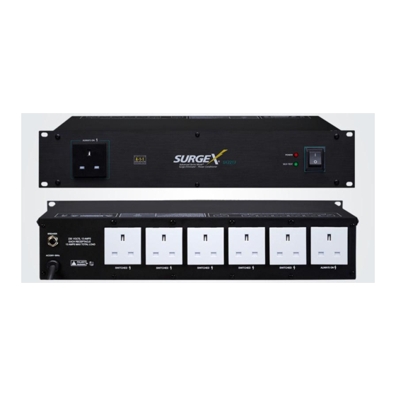
Ametek SurgeX SX2213 설치 지침 - 페이지 4
{카테고리_이름} Ametek SurgeX SX2213에 대한 설치 지침을 온라인으로 검색하거나 PDF를 다운로드하세요. Ametek SurgeX SX2213 5 페이지.

CAUTION:
Do not repeatedly turn an RT / RL product
on-off-on-off with a heavy load connected. The ICE
circuitry absorbs the inrush energy each time the unit is
turned on and may overheat if this is done repeatedly in
a short period of time. Wait one minute between repeated
on/off cycles.
Remote Control (RT Products Only)
Remote control connections are wired to the green 7-pin
plug-in Phoenix terminal block on the rear of the unit next to
the power cord. The terminal block is shipped with a jumper
wire between pins 1 & 2 so that the unit can be used without
a remote control connection. If you will be using a remote
control you will first need to remove this jumper wire. You can
unplug the terminal block to make connections and after you
have made the connections to the terminal block, plug it back
into the connector on the rear of the unit. Never solder (tin)
wires before inserting into a terminal block – solder cold flows
and you will eventually have loose connections!
The connections are as follows:
Pin 1 -- Contact Closure
Pin 2 -- Contact Closure / Applied Voltage +
Pin 3 -- Applied Voltage -
Pin 4 -- Remote LED +
Pin 5 -- Remote LED -
Pin 6 -- Aux Relay Contact
Pin 7 -- Aux Relay Contact
Control Connections
Control of the switched receptacles can be accomplished by
using a switch (contact closure), another SurgeX
or by an applied voltage (5 to 30 volts DC). When using a
switch, choose a switch with gold contacts for the best long
term reliability.
Connections are made to terminal block pins 1, 2 & 3 as
follows:
•
Connect switch contacts, a contact closure, or SurgeX
control to pins 1 and 2.
Or:
•
Connect an applied DC voltage to pins 2 and 3. The
positive must be connected to pin 2 and the negative
must be connected to pin 3.
© 2019 AMETEK Electronic Systems Protection
Remote Indicator LED
®
Connecting the Remote LED is optional. An LED connected to
pins 4 and 5 will indicate when the switched receptacles are
on. 10mA of current is available at this output, but you must
use a series resistor if you are using your own LED. For
most LEDs a 1K resistor will provide suitable brightness. If you
need less brightness use a larger value of resistor, and if you
need more brightness use a smaller value of resistor.
•
Connect the LED positive wire to Pin 4
•
Connect the LED negative wire to Pin 5
Auxiliary Relay Contacts
The auxiliary relay contacts, pins 6 & 7, provide a way to
cascade units or to provide confirmation feedback to a central
controller. When the switched receptacles are on, the aux
relay contacts are closed. There is a 1 second delay before
the aux relay closes which gives time for the SurgeX
Current Elimination (ICE
in combination with the SurgeX
to sequence the power to several large loads (such as
amplifiers) because of inrush current. SurgeX
when cascaded, can turn on a bank of large amplifiers with
no inrush current, and therefore no risk of blowing a circuit
breaker.
To cascade two or more RT products, connect the aux relay
contacts of one unit to the contact closure input of the next
unit. To provide confirmation feedback, connect the aux relay
contacts to an input on the central controller.
The relay contacts are rated for 1 amp at 30 V DC.
®
RT product,
®
UM-SX2200-Rev-B
®
) circuit to operate. This short delay
®
®
ICE
makes it unnecessary
®
RT products,
surgex.com
®
Inrush
