Asus 90MB14Z0-M0EAY0 매뉴얼 - 페이지 11
{카테고리_이름} Asus 90MB14Z0-M0EAY0에 대한 매뉴얼을 온라인으로 검색하거나 PDF를 다운로드하세요. Asus 90MB14Z0-M0EAY0 30 페이지.

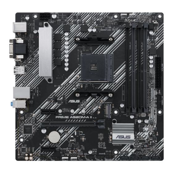
8. USB 3.2 Gen 1 header
The USB 3.2 Gen 1 header allows you to connect a USB 3.2 Gen
1 module for additional USB 3.2 Gen 1 ports. The USB 3.2 Gen 1
header provides data transfer speeds of up to 5 Gb/s.
The USB 3.2 Gen 1 module is purchased separately.
9. USB 2.0 headers
The USB 2.0 headers allow you to connect USB modules for additional USB
2.0 ports. The USB 2.0 headers provide data transfer speeds of up to 480 Mb/s.
DO NOT connect a 1394 cable to the USB connectors. Doing so will
damage the motherboard!
The USB 2.0 module is purchased separately.
10. Clear CMOS header
This header allows you to clear the CMOS RTC RAM data of the system setup information
such as date, time, and system passwords.
To erase the RTC RAM:
1.
Turn OFF the computer and unplug the power cord.
2.
Use a metal object such as a screwdriver to short the two pins.
3.
Plug the power cord and turn ON the computer.
4.
Hold down the <Del> key during the boot process and enter BIOS setup to re-
enter data.
If the steps above do not help, remove the onboard battery and short the two pins again to
clear the CMOS RTC RAM data. After clearing the CMOS, reinstall the battery.
11. COM Port header
This header is for a serial (COM) port. Connect the serial port module cable to
this header, then install the module to a slot opening at the back of the system
chassis.
12. Front panel audio header
This header is for a chassis-mounted front panel audio I/O module that
supports HD audio standard. Connect one end of the front panel audio
I/O module cable to this header.
•
We recommend that you connect a high-definition front panel
audio module to this header to avail of the motherboard's high-
definition audio capability.
•
If you want to connect a high-definition front panel audio
module to this header, set the Front Panel Type item in the
BIOS setup to [HD Audio]. By default, this header is set to [HD
Audio].
ASUS PRIME A520M-A
PIN 1
USB3+5V
USB3+5V
IntA_P1_SSRX-
IntA_P2_SSRX-
IntA_P1_SSRX+
IntA_P2_SSRX+
GND
GND
IntA_P1_SSTX-
IntA_P2_SSTX-
IntA_P1_SSTX+
IntA_P2_SSTX+
GND
GND
IntA_P1_D-
IntA_P2_D-
IntA_P1_D+
IntA_P2_D+
GND
PIN 1
CLRTC
PIN 1
COM
PIN 1
AAFP
HD-audio-compliant
pin definition
1-3
