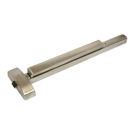
Dorex 8500 Series 설치 지침
{카테고리_이름} Dorex 8500 Series에 대한 설치 지침을 온라인으로 검색하거나 PDF를 다운로드하세요. Dorex 8500 Series 2 페이지. Panic rim
Dorex 8500 Series에 대해서도 마찬가지입니다: 설치 지침 (2 페이지)

TOP STRIKE
TOP LATCH
WOOD OR
MACHINE
SCREWS
TOP ROD
CAUTION:
Exit device components must be
installed flush to a flat surface
ROD GUIDE
WOOD OR
MACHINE
SCREWS
HOLLOW
ROD
RIVET
ADAPTER
STRIKE FILLER
PLATE
ON FRAME
MAIN
CHASSIS
ROD
ADAPTER
HOLLOW
RIVET
LATCH FILLER
PLATE
ON DOOR
ROD
GUIDE
WOOD OR
MACHINE
BOTTOM
SCREWS
ROD
NOTE:
Install bottom rod first
WOOD OR
BOTTOM
LATCH
BOTTOM
STRIKE
INSTALLATION INSTRUCTIONS FOR VERTICAL PANIC MODEL
COVER
WOOD OR
COVER
MACHINE
SCREWS
MACHINE
COVER
SCREWS
GENERAL NOTES
Before installing exit device, verify or note the following:
1. The door surface must be flat and properly reinforced
at the exit device mounting locations.
If door is not reinforced, the door surface may collapse
or bow-in, causing malfunction in the exit device
operation.
2. Door must be properly fitted and hung.
3. The 3' exit device model can be cut to fit doors from
30 to 38" (762 to 965 mm) in width.
The 4' exit device model can be cut to fit doors from
38 to 48" (965 to 1219 mm) in width
4. Determine door handing (see illustration below).
5. For wood doors or hollow metal doors use through bolts
(not supplied), and for metal reinforced doors drill & tap and
use machine screws. (Refer to Template document).
DOOR HANDING
RIGHT HAND REVERSED
END SUPPORT
BRACKET
WOOD OR
MACHINE SCREWS
INSTALLATION STEPS OF ROD ADAPTER & RODS
NOTE:
Complete the installation of exit device
chassis and top and bottom latches
as per template and assembly
instructions before installing rods
A
B
Install the rod guide at the
central position of the rod
C
NOTE:
Install bottom rod first
A:
Top strike and shims
(if necessary)
B:
Top latch
C:
Head assembly
D:
Bottom latch
D
E:
Bottom strike and shims
(if necessary)
F:
End support bracket
E
EACH SET CONTAINS THE FOLLOWING PARTS
LEFT HAND REVERSED
BAG: PARTS INCLUDED:
1.
Upper strike & screws
2.
Bottom strike & screws
3.
Head & end cover chassis screws
4.
Latch & strike filler plate screws
5.
Upper & bottom chassis screws
6.
Hollow rivets
7.
2 Rod Guides with screws
TOP ROD CUTTING GUIDE:
DOOR HEIGHT:
84" ............................. 35 ¼"
END
83 ½".......................... 34 ¾"
COVER
83" ............................. 34 ¼"
82 ½".......................... 33 ¾"
82" ............................. 33 ¼"
81 ½".......................... 32 ¾"
81" ............................. 32 ¼"
80 ½".......................... 31 ¾"
80" ............................. 31 ¼"
1
2
3
4
F
5
6
TOP ROD LENGTH:
Tightly turn the rod adapter
on head assembly on both
ends (top and bottom)
Install the bottom rod (short rod)
to the bottom latch assembly by
screwing the rod into the
threaded bolt completely
(not tightly)
Without pressing the push bar,
align rod beneath installed rod
adapter, then unscrew the
bottom rod upwards until the
rod inserts into "cup" of the rod
adapter. Align holes and fix with
hollow rivet (use pliers to
"squeeze" the exposed rivet end)
Be sure to activate small lever
above top latch to raise latch
wedge and drop threaded bolt
before proceeding.
Install the top rod (long rod) to
the top latch assembly by screwing
the rod into the threaded bolt
completely (not tightly)
Without pressing the push bar,
align rod above installed rod
adapter, then unscrew the top
rod downwards until the rod
inserts into "cup" of the rod
adapter. Align holes and fix with
hollow rivet (use pliers to
"squeeze" the exposed rivet end)
Be sure to screw locknut on latch
bolt (both top and bottom)
against both rods and tighten to
lock rod into position.
8500VP-INS 2018-11
