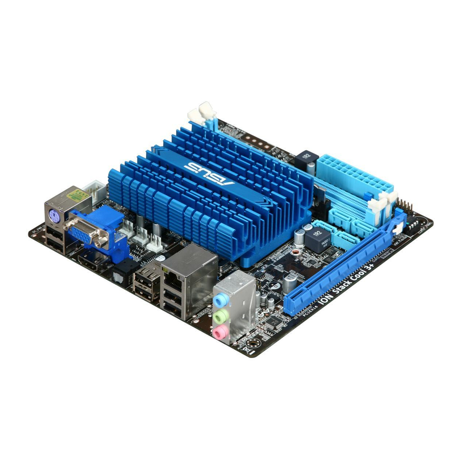
Asus AT3IONT-I DELUXE 사용자 설명서 - 페이지 11
{카테고리_이름} Asus AT3IONT-I DELUXE에 대한 사용자 설명서을 온라인으로 검색하거나 PDF를 다운로드하세요. Asus AT3IONT-I DELUXE 48 페이지. Asus computer hardware

1.2
Motherboard overview
1.2.1
Motherboard layout
ASUS AT3IONT-I Series motherboards include AT3IONT-I and AT3IONT-I DELUXE two
models The layout varies with models. The layout illustrations in this user guide are for
AT3IONT-I DELUXE only.
Ensure that you install the motherboard into the chassis in the correct orientation. The edge
with external ports goes to the rear part of the chassis.
Place this side towards
the rear of the chassis.
Place four screws into the holes indicated by circles to secure the motherboard to the
chassis. DO NOT overtighten the screws! Doing so can damage the motherboard.
1.2.2
Layout contents
Connectors/Jumpers/Slots/LED
CPU, power, and chassis fan connectors (3-pin
1.
CPU_FAN, 3-pin PWR_FAN, 3-pin CHA_FAN)
2.
Serial port connectors (10-1 pin COM1)
3.
Atom 330 processor
4.
DDR3 DIMM slots
5.
SATA power connectors (4-pin SATA_PWR1)
6.
Chassis intrusion connector (4-1 pin CHASSIS)
ASUS AT3IONT-I Series
1
2
COM1
DC_PWR/
WiFi
Antenna
KB_USB56
Super
I/O
CPU_FAN
PWR_FAN
CHA_FAN
SPDIF_O
BT_USB34
LAN1_USB12
RTL
8112L
RCA_OUT
AAFP
AUDIO
ALC
887
12
11
Page
1-13
7.
1-15
8.
1-3
9.
1-3
10.
1-12
11.
1-14
12.
3
17.1cm(6.75in)
Intel
®
Atom 330
NVIDIA
®
ION
WLAN
PCIEX16
10
9
Connectors/Jumpers/Slots/LED
System panel connector (10-1 pin
F_PANEL)
Clear RTC RAM (3-pin CLRTC)
Onboard LED (SB_PWR)
Serial ATA connectors (7-pin SATA1,
SATA2, SATA3, SATA4)
Front panel audio connector (10-1 pin
AAFP)
USB connector (10-1 pin USB78, USB910)
4
5
6
7
8Mb
BIOS
8
Page
1-14
1-8
1-1
1-11
1-13
1-12
1-2
