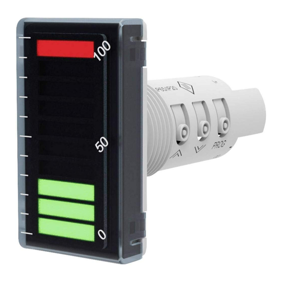
Akytec ITP15 사용자 설명서 - 페이지 5
{카테고리_이름} Akytec ITP15에 대한 사용자 설명서을 온라인으로 검색하거나 PDF를 다운로드하세요. Akytec ITP15 10 페이지. Led bargraph indicator

Press the release lever to free the wire.
–
The electrical connections are shown in Fig. 5.5-5.6 and the terminal assignments in
Table 5.1.
–
Connect the power supply to the terminals 24V+ / 24V-.
–
Ensure that the device is provided with its own power supply line and electric fuse I = 0.5
A.
–
The maximum conductor cross-section is 1 mm². Wires should be stripped for approx. 8-
10 mm.
5.1.1
Table 5.1 Terminal assignment
5.1.2
The NPN transistor output is designed to control the low voltage relay up to 42 V DC / 200
mA
►
As a precaution against inadvertent current reversal on output, a parallel diode (U
NOTICE
≥ 1.3U, I
akYtec GmbH · Vahrenwalder Str. 269 A · 30179 Hannover · Germany Tel.: +49 (0) 511 16 59 672-0 ·
Fig. 5.3 Disconnecting the wire
Input
Designation
24VDC -
24VDC +
Output
≥ 1.3I) is usually included in the output circuit.
VD
Fig. 5.6 NPN transistor output
Fig. 5.5 Input wiring
Description
Power supply
DO-
Output -
DO+
Output +
COM
Common -
U+
Voltage input +
I+
Current input +
_
DO-
K
+
DO+
VD
Fig. 5.4 Mounting
U
U
www.akytec.de
VD
4
