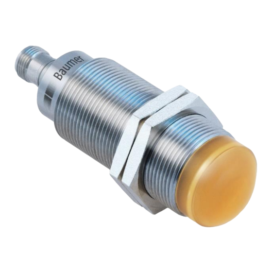
Baumer IO-Link RR30 사용 설명서 - 페이지 16
{카테고리_이름} Baumer IO-Link RR30에 대한 사용 설명서을 온라인으로 검색하거나 PDF를 다운로드하세요. Baumer IO-Link RR30 40 페이지. Radar sensor

4.3.7.1 Response Delay Time
The response delay time defines the time, the measurement value needs to be above (single point mode) or
inside (window mode) the switch points of the related SSC until its status changes to active (or inactive, if the
logic is inverted as described in section 4.3.4)
When to apply?
To avoid the detection of small peaks/false switching operations due to structure changes of the
-
background or similar.
To avoid wrong switching of known disturbances such as the wheel of a mixer
-
To avoid bouncing.
-
To optimize the timing of the execution of a subsequent actor triggered by the output of the sensor.
-
Parameter name
Response Delay.SSC1 Time
4.3.7.2 Release Delay Time
The release delay time defines the time, where the measurement value needs to be below (single point) or
outside (window mode) of the switch points of the related SSC, until its status is changed to inactive (or
active, if the logic is inverted as described in section 4.3.4)
When to apply?
en_BA_RR30_IO-Link_V0.23.docx
13.01.2021/
Figure 19: Response Delay
Short Description
Sets / indicates the response delay
time in milliseconds for the
respective switching signal channel
(SSC).
16/40
Rights
Unit /
Allowed
values
rw
0 to 60000 ms
Default: 0 ms
Baumer Electric AG
Frauenfeld, Switzerland
