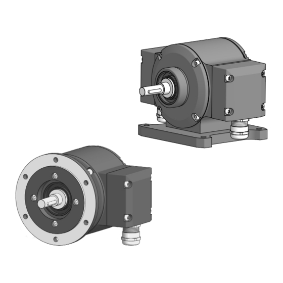
Baumer PMG10P 설치 및 작동 지침 - 페이지 18
{카테고리_이름} Baumer PMG10P에 대한 설치 및 작동 지침을 온라인으로 검색하거나 PDF를 다운로드하세요. Baumer PMG10P 32 페이지. Absolute encoder
Baumer PMG10P에 대해서도 마찬가지입니다: 설치 및 작동 지침 (32 페이지), 설치 및 작동 지침 (36 페이지), 운영 매뉴얼 (44 페이지), 운영 매뉴얼 (44 페이지), 운영 매뉴얼 (40 페이지), 운영 매뉴얼 (40 페이지), 운영 매뉴얼 (40 페이지), 운영 매뉴얼 (36 페이지)

ELECTRICAL CONNECTION / SWITCHING CHARACTERISTICS – SPEED SWITCH (OPTION)
5.6
Switching characteristics – speed switch (option)
i
The factory setting of the switching speed for the PMG10P is 6000 rpm� The PMG10
without programming interface is delivered with the individually ordered fixed swit-
ching speed�
Event
During initialisation
After initialisation and
speed ≤ -ns (off)
-ns (off) < speed ≤ -ns (on)
-ns (on) < speed < +ns (on)
+ns (on) ≤ speed < +ns (off)
+ns (off) ≤ speed
High resistance
Resistance between
SP+ and SP-
Low resistance
n
= Speed
+ns (off) = Switch-off speed at shaft rotation in positive rotating direction*
-ns (off) = Switch-off speed at shaft rotation in negative rotating direction*
Switching hysteresis
+ns (on) = Switch-on speed at shaft rotation in positive rotating direction*
-ns (on) = Switch-on speed at shaft rotation in negative rotating direction*
* See
section 7, page
18/32
-n
-ns (off)
: 10...100 % (factory setting = 10 % min. 1 Digit)
26�
MB261EN - 11196414, 21A1, Baumer_PMG10-Inc_EN_202103_MI_11196414
State of the speed switch output
High resistance (overspeed)
High resistance (overspeed)
State unchanged
Low resistance (no overspeed) after initialisation if
the device is rotating between the switching range
during initialisation�
Low resistance (no overspeed)
State unchanged
Low resistance (no overspeed) after initialisation if
the device is rotating between the switching range
during initialisation�
High resistance (overspeed)
-ns (on)
0
+ns (on)
+ns (off)
+n
