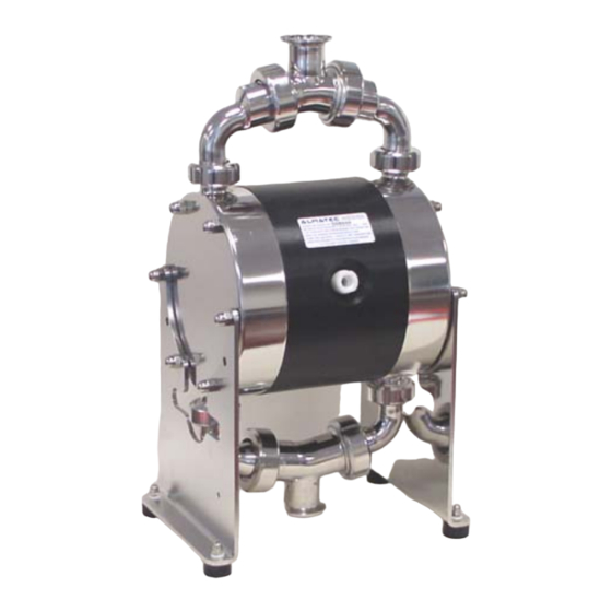
Dover Almatec Biocor B 32 Series 작동 및 설치 지침 - 페이지 7
{카테고리_이름} Dover Almatec Biocor B 32 Series에 대한 작동 및 설치 지침을 온라인으로 검색하거나 PDF를 다운로드하세요. Dover Almatec Biocor B 32 Series 10 페이지.

Disassembly
The general design of the ALMATEC BIOCOR pumps is simple. A plastic tool designed for the mounting of
the air-valve [22] is delivered along with every pump. Further special tools are not required. Please find the
part number for any part in the spare part list.
•
Before starting to disassemble the pump, take care that the pump has been emptied
and rinsed. Further the pump has to be cut off from any energy on the air and product
side. If the pump is being removed from the plant, a reference sheet about the delivered
liquid has to be attached.
•
Please respect the relevant additional security advices, if the pump has been used for
aggressive, dangerous or toxic liquids.
•
Before putting the pump back into operation, the tightness of the pump has to be
checked.
First unscrew the muffler [25] out of the center block [20]. Loosen the four union nuts of the suction and
discharge ports [4,6] with a hook wrench (figure 7.1), but do not unscrew complete. Loosen the two union
nuts, which connect the two pipe bends discharge side [5] with the pump housings [1], to take off the whole
discharge side of the pump. Remove O-rings pump housing [2]. Lay the pump on its back and unscrew the
nuts of the housing bolts [8,9] on one side using a socket wrench and take off the frame [4]. Loosen the two
union nuts, which connect the two pipe bends suction side [3] with the pump housings [1], to take off the
whole suction side of the pump. Remove O-rings pump housing [2] followed by the pump housing [1] itself.
So the complete discharge side, one pump housing [1], one frame [7] and the complete suction side are
dismantled (figure 7.2). Turn off the union nuts at the suction and discharge sides, so that the pipe bends
[3,5] and the suction and discharge ports [4,6] are separated. Remove valve stops [17], O-rings valve stop
[19] and valve balls [16].
figure 7.1
Work carefully to ensure that the sealing surfaces in contact to the diaphragms are not damaged. Screw one
diaphragm [15] left-turning off the shaft [13]. Carefully pull out the housing bolts [8,9], so the second pump
housing [1] and the second frame [7] are also dismantled. Take the other diaphragm [15] along with the
shaft [13] out of the center block [20]. Unscrew the set screws shaft [14] off the diaphragms [15] (figure 7.3).
Remove piston rings and O-rings of the shaft piston rings [21] from their grooves carefully (figure 8.1); do
not damage the edges in the center block [20]. A re-assembly of the same piston rings is impossible, they
have to be replaced. Unscrew the air inlet [23] and the air filter [24] out of the center block [20]. To remove
®
the PERSWING P
air control system [22], screw off both end caps using the plastic mounting tool supplied
with the pump (figure 8.2). Take out main and pilot piston. Push out the air valve housing with the mounting
tool turned around (figure 8.3).
figure 7.2
figure 7.3
7
