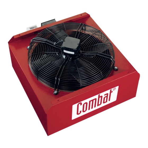
COMBAT HVE 400 설치, 운영 및 서비스 매뉴얼 - 페이지 8
{카테고리_이름} COMBAT HVE 400에 대한 설치, 운영 및 서비스 매뉴얼을 온라인으로 검색하거나 PDF를 다운로드하세요. COMBAT HVE 400 12 페이지. Energy saving fans with control options

DANGER
Electrical Shock Hazard
Disconnect electrics before service
Equipment must be properly grounded.
Failure to follow these instructions can result in
death or electrical shock
FIGURE 5: ME1.10 Speed Controller Wiring
Diagram
ME1.10 SPEED CONTROLLER
WIRING CONNECTIONS TO HVE
HVE
FAN
ME1.10 SPEED
STAT
CONTROLLER
L
N Z
U UZ
N L 1 2 3
FUSE
SPUR
FUSE
SPUR
230VAC
SUPPLY
FIGURE 7: HVE Fan Without Speed Control
Wiring Diagram
Model/Part Numbers
Model
HVE400
Axial Fan 400mm
HVE450
Axial Fan 445mm
HVE650
Axial Fan 650mm
N/A
Thermostat 230V
8
Section 5
HVE
FAN
STAT
N L 1 2 3
FUSE
SPUR
REF NOTES FOR NUMBER OF HVE TYPE
FANS PERMITTED PER MODEL SIZE
N.B.
HVE 650 X 2 MAX
HVE 450 X 2 MAX
HVE 400 X 8 MAX
Description
Part Number
90750008
90750004
A269
C2334B
Combat Limited HVE Energy Saving Fans, Installation, Operation and Service Manual
Typical
External Wiring Diagrams
5.1 External Wiring Connection Details
If any of the original wiring supplied with the fan has to
be replaced, it must be replaced with wiring material
having a temperature rating of at least 105°C and 600V.
FIGURE 6: WAC6 Fan Control Wiring Diagram
FIGURE 8: Internal components Diagram
