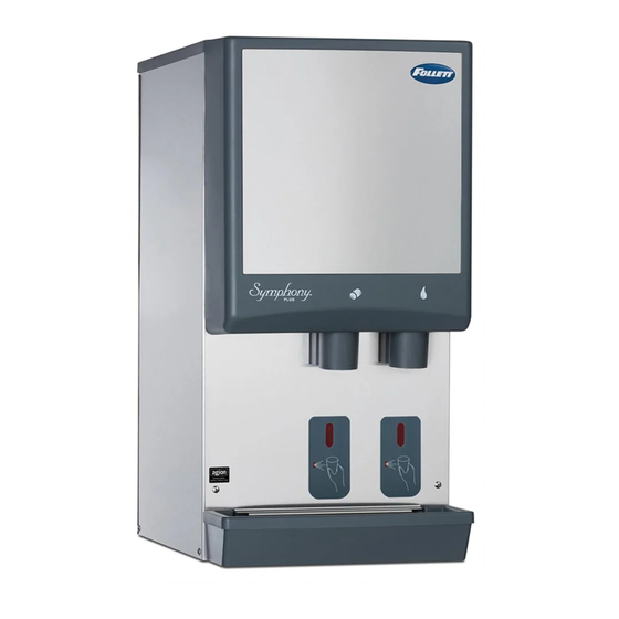
Follett 50CI425A 설치 매뉴얼 - 페이지 6
{카테고리_이름} Follett 50CI425A에 대한 설치 매뉴얼을 온라인으로 검색하거나 PDF를 다운로드하세요. Follett 50CI425A 17 페이지. Ice and water dispensers

Installing countertop dispensers with bottom
exiting utilities
WARNING!
§ A sturdy work surface capable of supporting the
entire dispenser must be used.
§ The work surface must be large enough to
accommodate height of dispenser.
§ Failure to provide proper support may result in
personal injury.
1. Position dispenser with dispense chutes facing
upward on sturdy work surface (Fig. 3).
2. Move drain fitting from back of dispenser and
mount (Fig. 4.1).
3. Cut drain tube to length and attach to barbed
connection (Fig. 4.2).
4. Move inlet water fitting from back of dispenser
and mount (Fig. 4.3).
5. Cut water tubing to length and re-insert into
water fitting.
6. Water-cooled only. Disconnect internal
condenser water inlet and outlet fittings.
7. Water-cooled only. Relocate water inlet and
outlet fittings and reconnect (Fig. 4.4). Note:
The water inlet is connected to the condenser;
the outlet line is connected to the water
regulating valve.
8. Remove the drain plug from the internal drain
line connection point and relocate to back of
dispenser and reconnect.
9. Raise the dispenser upright and position in
desired location.
10. Mark dispenser outline on counter and remove
dispenser.
11. Cut countertop utility opening and drill four
7/16" holes to anchor dispenser to counter
(Fig. 5).
12. Apply a thick bead approximately 1/4" (7 mm)
diameter of NSF-listed silicone sealant (Dow
Corning* RTV-732 or equivalent) 1/4" (7 mm)
inside marked outline of dispenser.
13. Reposition dispenser on counter and secure to
counter with four 3/8"-16NC bolts.
14. Smooth excess sealant around outside of
dispenser and make utility connections
through countertop cutout.
§ Do not connect water-cooled condenser outlet line
to the dispenser drain line.
15. Turn on water supply and check for leaks.
16. Clean dispenser and ice machine.
17. Turn power on and allow ice machine to
produce ice.
6
25CI425A/W, 25HI425A, 50CI425A/W, 50HI425A
CAUTION
Fig. 3
Fig. 4
2
TRIM DRAIN TUBE FOR
NEW DRAIN FITTING
LOCATION.
1
5
Fig. 5
21.00"
(53.3 cm)
4X
20.00"
Ø.375"
(50.8 cm)
1.56"
(10 mm)
(4.0 cm)
hole
Cutout
14.00"
connections
(35.6 cm)
through
bottom
16.00"
(40.7 cm)
5.00"
(12.7 cm)
min.
3
4
Water cooled
only
0.50"
(13 mm)
1.56"
(4.0 cm)
2.50"
16.50"
(6.36 cm)
(41.9 cm)
12.50"
(31.8 cm)
7.00"
(17.8 cm)
