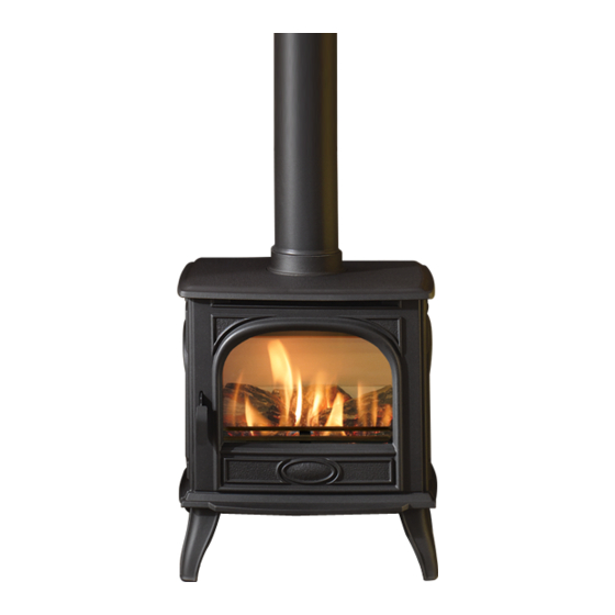
Dovre 280 사용 지침 설치 및 서비스 - 페이지 10
{카테고리_이름} Dovre 280에 대한 사용 지침 설치 및 서비스을 온라인으로 검색하거나 PDF를 다운로드하세요. Dovre 280 12 페이지.

Servicing Instructions
6.2
Disconnect the 2 x wires connecting the 2 x 'flying' LEDs
to the front LED board, noting their orientation.
6.3
Lift and rotate the motor unit to give access to the rear
LED board.
6.4
Disconnect both wires from the rear LED board, noting the
orientation.
6.5
Unplug the cables connecting the motor unit and the PCB.
6.6
The motor and effects unit can now be removed and
replaced as a whole unit.
6.7
Replace in reverse order. Ensure to replace gaskets when
reattaching motor to appliance body and that all wires are
correctly connected.
7. Replacing the Middle LED Board
7.1
The middle LED board is attached to the motor unit but can
be replaced individually, see Diagram 7.
7
Middle
LED
board
7.2
Disconnect the wire connecting the middle LED board to the
rear LED board, noting its orientation.
7.3
Attach the new board and reconnect the wire.
8. Replacing the Rear LED Board
The rear LED board is attached to the motor unit but can be
replaced individually, see Diagram 7.
8.1
Remove the motor unit following instructions in section 6 (it
is not necessary to disconnect the motor unit from the
PCB) and rotate to access the rear LED board.
8.2
Release the board by removing the 2 x screws at either
end of it.
8.3
Disconnect the wire connecting the rear LED board to the
front LED board, noting its orientation.
8.4
Attach the new board using the 2 x screws and reconnect
the wire.
8.5
Replace motor and effects unit (see Section 6). Ensure to
replace gaskets when reattaching motor to appliance
body and that all wires are correctly connected.
10
Rear LED board
9. Replacing the Heater Assembly
9.1
To access the heater assembly remove any loose top plates
or panels before moving the appliance and carefully lay the
appliance on its back.
9.2
Remove the 5 x screws securing the heater casing to the
bottom of the firebox, see Diagram 8.
8
Screws
Bottom of Firebox
9.3
Remove the 4 x screws from the front of the heater casing,
see Diagram 9 to free the heater assembly.
9
9.4
Tilt the heater casing forward and carefully remove the
heater assembly, see Diagram 10.
10
Heater Assembly Case
Screws
