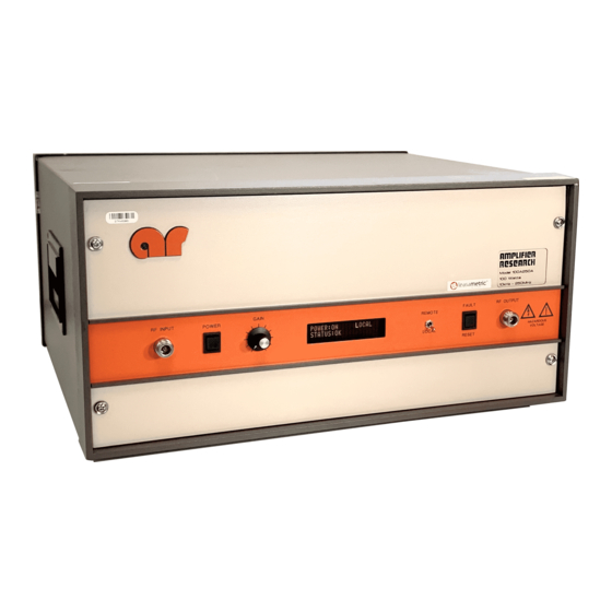
Amplifier Research 100A250 series 매뉴얼 - 페이지 9
{카테고리_이름} Amplifier Research 100A250 series에 대한 매뉴얼을 온라인으로 검색하거나 PDF를 다운로드하세요. Amplifier Research 100A250 series 19 페이지.

Model 100A250A
2.2.2 Remote Operation (continued)
2.2.2.6
IEEE-488 Communications (continued)
IEEE-488 Serial Poll
Response (STB)
(binary/decimal)
(01000001) 65
(01000010) 66
(01000100) 68
(01001000) 72
(01010000) 80
2.2.2.7
RS-232 Communications
If the RS-232 interface is active, the Model 100A250A will test for a properly connected RS-232
interface when it is switched into the remote operation mode. In order for the Model 100A250A to
recognize an RS-232 connection, the "Data Carrier Detect" (DCD) line must be asserted. This line
is sampled continuously to determine if the RS-232 connection is broken; therefore, it must remain
asserted in order for the RS-232 interface to function. The "Clear To Send" (CTS) line is also used
to gate information from the Model 100A250A. This line must be asserted in order to receive
information from the Model 100A250A. The CTS line can be used as a "handshake" line to
inform the Model 100A250A when it is permissible to send information. If the CTS line is de-
asserted in the middle of a transmission, the character in the process of being transmitted will be
completed and further transmission will halt until the CTS line is re-asserted.
Model 100A250A itself asserts two lines: "Data Terminal Ready" (DTR) and "Request To Send"
(RTS). The DTR line is continuously asserted, while the RTS line is used to gate information into
the Model 100A250A. Connector pin-out information is given in Table 2-3.
Table 2-2
Remote Error Codes/Messages
Model 100A250A FAULT
BPM FAULT
THERMAL FAULT
INTERLOCK FAULT
PS1 FAULT
PS2 FAULT
Manual Text
RS-232
Error
Message
E1
E2
E3
E4
E5
The
2-5
REV -
